Sampling device and sampling method for measuring initial visbreaking moisture content of cutter head interface

A sampling device and water content technology, which are applied in the field of viscosity reduction design and anti-sticking of metal parts surface, can solve the problems of soil disturbance damage, unevenness, and the inability of thin layer soil to keep the shape, so as to reduce disturbance damage and improve accuracy. sexual effect

Active Publication Date: 2022-06-03
NANJING FORESTRY UNIV
View PDF6 Cites 0 Cited by
  • Summary
  • Abstract
  • Description
  • Claims
  • Application Information

AI Technical Summary

Problems solved by technology

Existing test methods often focus on directly pulling out the test plate to measure the adhesion force between the soil and the metal interface. The soil after pulling out has been disturbed and damaged, especially the thin layer of soil near the interface. Unable to maintain a specific shape, very uneven, unable to achieve effective extraction of thin layers of soil on the metal cutterhead surface and accurate measurement of moisture content
[0005] Therefore, the existing technology cannot guarantee the measurement of cutterhead adhesion while protecting the thin layer of soil near the interface from being disturbed and damaged, which restricts the accurate measurement of the initial viscosity-reducing moisture content of the cutterhead interface, let alone partitioning the cutterhead surface. Sampling and measuring the moisture content of the soil at different locations, so as to determine the distribution characteristics of the initial viscosity-reducing moisture content on the entire cutterhead surface; it is also impossible to determine the distribution characteristics of the initial viscosity-reducing moisture content under different degrees of visbreaking

Method used


Image

  • Sampling device and sampling method for measuring initial visbreaking moisture content of cutter head interface
  • Sampling device and sampling method for measuring initial visbreaking moisture content of cutter head interface
  • Sampling device and sampling method for measuring initial visbreaking moisture content of cutter head interface

Examples


Embodiment Construction

[0039] The present invention will be further described below with reference to the accompanying drawings and embodiments.

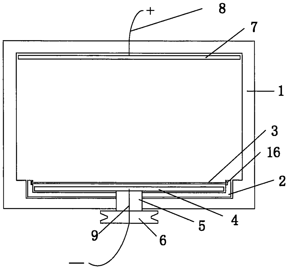
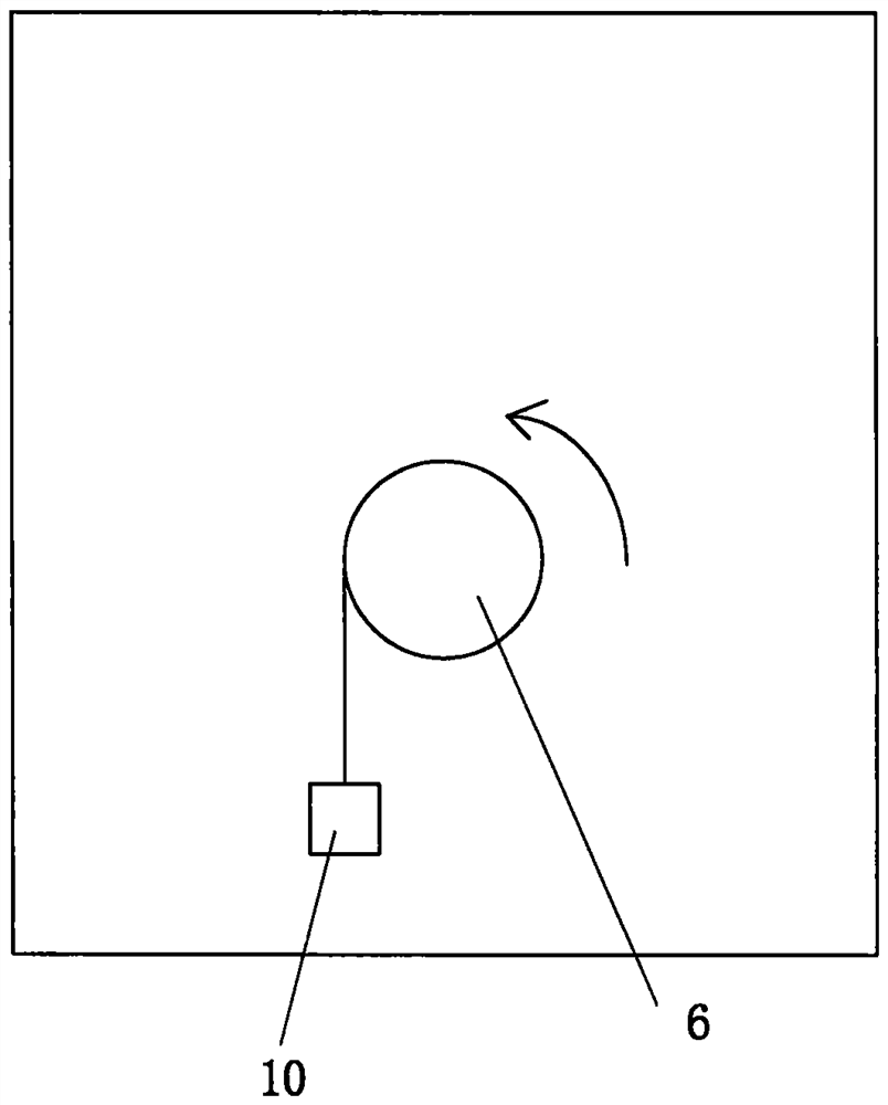
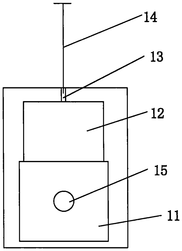
[0040] like Figure 1-Figure 3 As shown, the sampling device for measuring the initial viscosity reduction moisture content of the cutter head interface includes soil box 1, groove box 2, cutter 3, rotary cutter disc 4, rotating shaft 5, roller 6, metal plate 7, wire A 8 , wire B 9, weight 10 and pressure rod 14;

[0041] The soil box 1 and the groove box 2 are made of electrically insulating hard plastic materials;

[0042] The inner side of one side of the soil box 1 is provided with groove A 11, groove B 12, tunnel 13, pressure rod 14 and hole 15; the groove A 11 is allowed to be loaded into the groove box 2; the hole 15 allows the shaft 5 to pass through; The hole 13 allows the pressing rod 14 to pass through, and the cutter 3 can be cut downward from the position of the groove B 12 and pressed into the groove C 16 of the groove box 2;

[0043] The...


PUM


Abstract

The invention provides a sampling device and a sampling method for measuring initial visbreaking moisture content of a cutter head interface. The device comprises a soil box, a groove box, a cutter, a rotary cutting cutter head, a rotating shaft, a roller, a metal plate, a wire A, a wire B, a weight and a pressing rod, a groove A, a groove B, a hole channel, a pressing rod and a hole are formed in the inner side of one side of the soil box; a groove box is allowed to be arranged in the groove A; the hole channel allows the pressing rod to pass through, and the cutter can downwards cut soil; the rotary cutter head is connected with a roller on the outer side of the soil box through a rotating shaft, and a heavy object is suspended on a groove of the roller through a line; the rotary cutter head is connected to the cathode of the direct-current power supply; the metal plate is connected to the anode of the direct-current power supply; the cutter can integrally cut off extremely thin soil on the surface of the rotary cutter head, so that external soil is prevented from being mixed into the soil to influence the accuracy of measuring the water content of soil near an interface; and the distribution characteristics of the initial visbreaking moisture content of the surface of the whole cutterhead and the distribution characteristics of the initial visbreaking moisture content of the cutterhead under different visbreaking degrees can be determined.

Description

technical field [0001] The invention relates to anti-sticking and viscosity-reducing design technology on the surface of metal parts, in particular to a sampling device and sampling method for accurately measuring the interface moisture content after electroosmosis and viscosity-reducing of the interface between a metal cutter head and a soil body. Background technique [0002] It is a common phenomenon that the contact between the metal part and the soil with a certain moisture content will cause adhesion. In the shield construction operation, this adhesion phenomenon will bring extremely unfavorable consequences, such as the soil on the surface of the metal cutter head. The formation of a high-strength mud cake causes the cutter head and cutter to be wrapped, which cannot effectively cut the soil layer, resulting in a decrease in the efficiency of shield tunneling; The construction period, resulting in extremely unfavorable safety hazards, greatly increased the constructio...

Claims


Application Information

Patent Timeline
Patent Type & Authority Applications(China)
IPC IPC(8): G01N1/08
CPCG01N1/08
Inventor 刘成袁梦昕索坤宇蔡光华葛琦
Owner NANJING FORESTRY UNIV
Why Eureka
Try Eureka