
Automatic feeding auxiliary device suitable for chicken feed

A technology of automatic feeding and auxiliary devices, which is applied in applications, poultry farming, food processing, etc., can solve the problems of high labor intensity, low feed efficiency, and high cost, and achieve the goals of improving practicability, good feeding effect, and avoiding waste Effect

Inactive Publication Date: 2022-06-07
李虹
View PDF0 Cites 0 Cited by
  • Summary
  • Abstract
  • Description
  • Claims
  • Application Information

AI Technical Summary

Problems solved by technology

[0002] With the rapid development of the livestock and poultry breeding industry, breeding technology and supporting technologies have been vigorously promoted and applied. At present, large-scale farms are developing in the direction of factoryization, scale, intensification, and ecologicalization. However, such farms are equipped with The farming equipment used is automated, highly modernized, and expensive, while most small and medium-sized farms still use traditional artificial feeding methods
[0003] At present, in the traditional animal husbandry, in order to make the livestock grow better, people need to put grain feed on the livestock every day. The traditional method usually adopts the operation mode of artificial timing and fixed point feeding, but the manual feeding method takes up a lot of manpower Resources, manual labor intensity is high, the cost is high, not only time-consuming and laborious, but also unable to meet the needs of large-scale industrialized animal husbandry, and at the same time, the efficiency of feeding feed is low, and there are phenomena such as uneven feeding, so there are deficiencies and cannot meet the needs of users. demand, therefore, it is necessary to further improve the

Method used


Image

  • Automatic feeding auxiliary device suitable for chicken feed
  • Automatic feeding auxiliary device suitable for chicken feed
  • Automatic feeding auxiliary device suitable for chicken feed

Examples


Embodiment Construction

[0023] The present invention will be further described below in conjunction with the accompanying drawings:

[0024] as attached figure 1 to the attached Figure 4 shown:

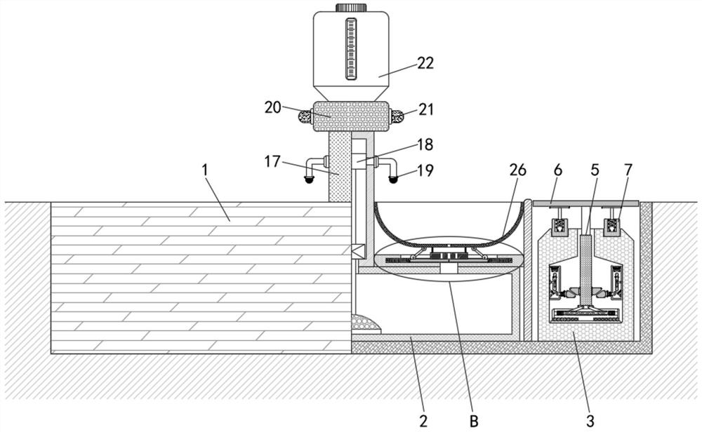
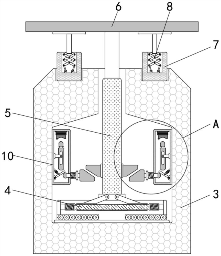
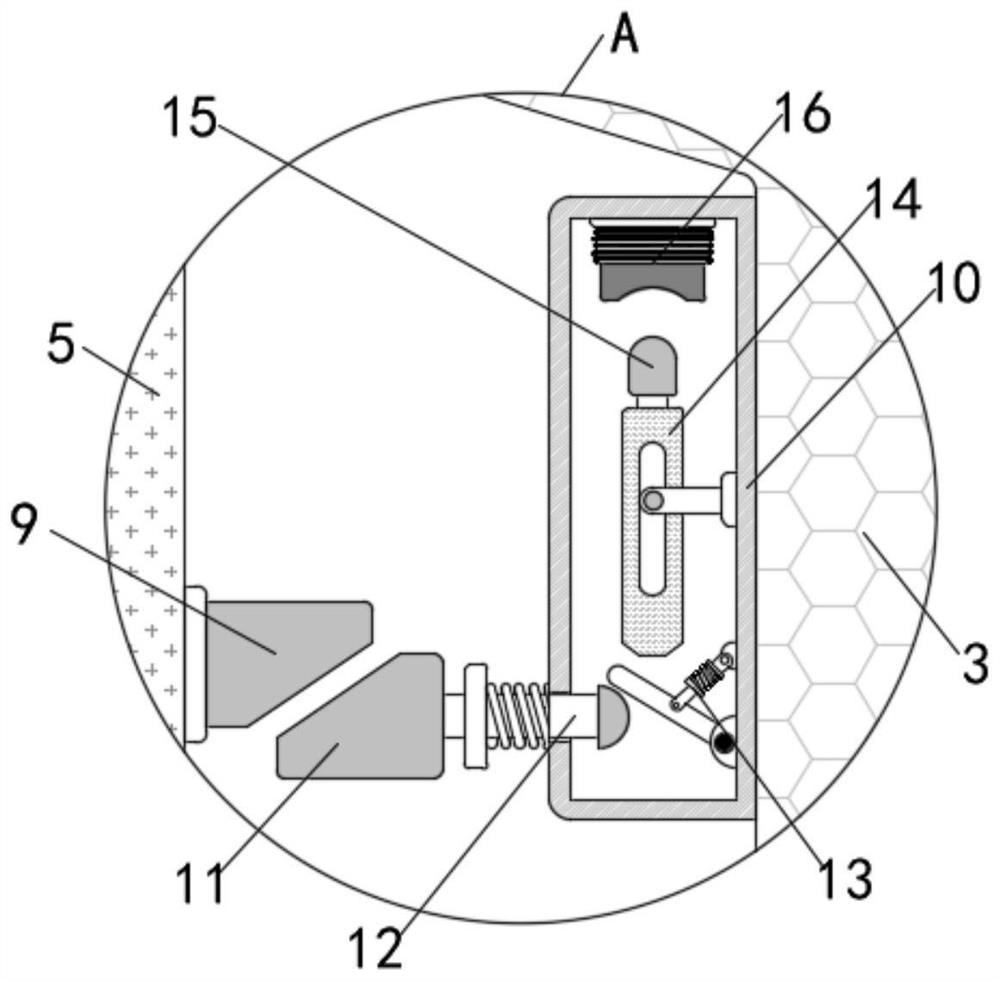
[0025] The present invention provides an auxiliary device for automatic feeding of chicken feed, which includes a main body 1, a water storage tank 2 and a support member 3 are installed inside the main body 1, and a support assembly 4 is installed inside the support member 3. The support assembly 4 The upper end of the support column 5 is fixedly installed with a support column 5, the top end of the support column 5 is fixedly installed with a bearing plate 6, an installation part 7 is installed on the upper side of the support part 3, and a support link 8 is installed inside the installation part 7, and the support link The upper end of 8 is fixedly connected with the bearing plate 6, further, a push block 9 is installed on the outer side of the support column 5, and a casing 10 is fixedly installed on ...


PUM


Abstract

The invention provides an automatic feeding auxiliary device suitable for chicken feed, which comprises a main body, a water storage tank and a supporting part are arranged in the main body, a supporting assembly is arranged in the supporting part, a supporting column is fixedly arranged at the upper end of the supporting assembly, a bearing plate is fixedly arranged at the top end of the supporting column, and a feeding device is fixedly arranged on the bearing plate. A mounting part is mounted on the upper side of the supporting part, and a supporting connecting rod is mounted in the mounting part. According to the automatic feeding auxiliary device suitable for the chicken feed, the chicken feed is stored in the feed storage tank, when the designated feeding time is reached, the driving device is used for spraying the chicken feed in the feed storage tank out of the spray heads, meanwhile, the sprayed chicken feed is evenly distributed on the periphery of the device, chicken flocks can eat the chicken feed conveniently, and the feeding efficiency is improved. And moreover, the damage caused by scrambling the feed among the chicken flocks can be effectively avoided, so that the chicken flocks achieve a better feeding effect.

Description

technical field [0001] The invention belongs to the technical field of feed feeding, and in particular relates to an automatic feeding auxiliary device suitable for chicken feed. Background technique [0002] With the rapid development of livestock and poultry breeding industry, breeding technology and supporting technology have been vigorously promoted and applied. At present, large-scale farms are developing in the direction of industrialization, large-scale, intensive and ecological development. However, such farms are equipped with The breeding equipment used is highly automated, modern and expensive, while most small and medium-sized farms still use traditional artificial feeding methods. [0003] At present, in traditional animal husbandry, in order to make the livestock grow better, people need to put grain feed on the livestock every day. The traditional method is usually the operation mode of manual feeding at regular and fixed points, but the manual feeding method ...

Claims


Application Information

Patent Timeline
Patent Type & Authority Applications(China)
IPC IPC(8): A01K39/04
CPCA01K39/04Y02P60/87
Inventor 李虹
Owner 李虹
Learn More