Supercharge Your Innovation With Domain-Expert AI Agents!

Cordless ultrasonic knife

An ultrasonic knife and knife head technology, applied in the field of medical devices, can solve the problems of uneven amplitude distribution, unstable contact, affecting work efficiency, etc., to achieve uniform amplitude distribution, improve efficiency, and improve work efficiency.

Pending Publication Date: 2022-06-07
苏州锐诺医疗技术有限公司
View PDF0 Cites 0 Cited by
  • Summary
  • Abstract
  • Description
  • Claims
  • Application Information

AI Technical Summary

Problems solved by technology

[0005] In order to solve the problems of unstable contact of various parts of the existing cordless ultrasonic scalpel and uneven amplitude distribution due to the shape of the cutter head, which further affects work efficiency, the present invention innovatively provides a cordless ultrasonic scalpel. The cutter head of the cordless ultrasonic scalpel The variable cross-section design is adopted and the length of the side cutting surface is longer than that of the main shaft. The amplitude distribution of the cutter head is uniform, and the cutting and hemostasis effects are good; the half-wavelength transducer and the handle shell always keep rolling contact, which reduces the vibration generated when the cutter head assembly rotates. Resistance, which minimizes resistance during rotation and improves efficiency; the positive and negative conductive rings are in elastic contact with the circuit board, and always keep in contact to ensure the stability of work and improve work efficiency

Method used


Image

  • Cordless ultrasonic knife
  • Cordless ultrasonic knife
  • Cordless ultrasonic knife

Examples


Embodiment Construction

[0034]The cordless ultrasonic knife provided by the present invention will be explained and described in detail below with reference to the accompanying drawings.

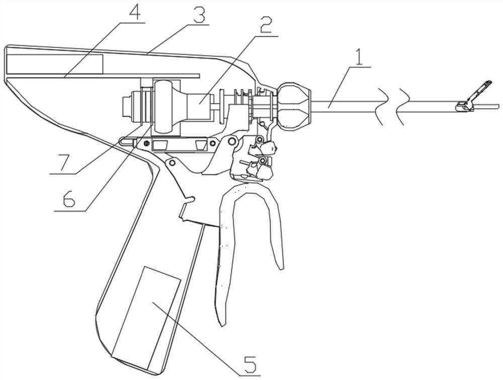
[0035] This embodiment specifically discloses a cordless ultrasonic knife, such as figure 1 As shown, it includes a cutter head assembly 1, a half-wavelength transducer 2, a handle housing 3, a circuit board 4 and a battery 5. The front end of the half-wavelength transducer 2 is threadedly connected with the cutter head assembly 1, so that the cutter head assembly 1 can be 360 ° rotation, thereby enabling the cutter head assembly 1 to rotate axially relative to the handle housing. The rear end of the half-wavelength transducer 2 is installed in the handle casing 3, the half-wavelength transducer 2 is in rolling contact with the handle casing 3, the circuit board 4 and the battery 5 are fixed in the handle casing 3, and the battery 5 is electrically connected to the circuit board 4 . like figure 1 As shown, the h...


PUM


Abstract

The cordless ultrasonic scalpel comprises a scalpel head assembly, a half-wavelength transducer, a handle shell, a circuit board and a battery, and a scalpel head of the scalpel head assembly is an elbow and is of a variable cross-section structure; the concave arc cutting surface on the side surface of the tool bit is longer than the concave arc cutting surface on the main shaft surface; the front end of the half-wavelength transducer is in threaded connection with the tool bit assembly, the rear end of the half-wavelength transducer is installed in the handle shell, the half-wavelength transducer is in rolling contact with the handle shell, the circuit board and the battery are fixed in the handle shell, the battery is electrically connected with the circuit board, the half-wavelength transducer is coaxially sleeved with an anode conducting ring and a cathode conducting ring, and the anode conducting ring is electrically connected with the cathode conducting ring. And the positive conducting ring and the negative conducting ring are respectively in elastic electric contact with the circuit board. The tool bit is uniform in amplitude distribution and good in cutting and hemostasis effects; resistance generated when the tool bit assembly rotates is reduced, and efficiency is improved; the positive and negative conducting rings are in elastic contact with the circuit board all the time, so that the working stability is ensured, and the working efficiency is improved.

Description

technical field [0001] The present invention relates to the technical field of medical devices, and more particularly, to a cordless ultrasonic knife. Background technique [0002] The principle of the ultrasonic knife is to use the ultrasonic transducer to generate vibration, the ultrasonic wave transmitted along the longitudinal axis of the tool bar, and then the amplitude-amplified vibration is generated on the tool bar along the axis, and finally the high-speed longitudinal mechanical motion is generated at the end of the tool head. The mechanical vibration of the tip of the cutter head is very effective in cutting soft tissue, and the heat generated by the ultrasonic high-frequency vibration can coagulate the tissue and close the blood vessels. Since the blade can easily reach the surgical site through the cannula, this instrument is especially suitable for minimally invasive surgery, such as endoscopic or laparoscopic surgery. The key to ultrasonic knife control is to...

Claims


Application Information

Patent Timeline
IPC IPC(8): A61B17/32
CPCA61B17/320068A61B2017/320082
Inventor 洪文亮张学武
Owner 苏州锐诺医疗技术有限公司
Features
  • R&D
  • Intellectual Property
  • Life Sciences
  • Materials
  • Tech Scout
  • Unparalleled Data Quality
  • Higher Quality Content
  • 60% Fewer Hallucinations
Learn More