Tracheal intubation mechanism and tracheal intubation robot

A tracheal intubation and intubation technology, applied in the field of medical devices, can solve the problems of missed rescue time, cross infection between doctors and patients, etc., to avoid secondary injuries, ensure the direction of progress, and reduce the risk of cross infection.

Pending Publication Date: 2022-06-07
胡晓旻
View PDF0 Cites 1 Cited by
  • Summary
  • Abstract
  • Description
  • Claims
  • Application Information

AI Technical Summary

Problems solved by technology

In the process of intubation, the doctor needs to be in close contact with the patient. During the opening process of the patient's airway, it is very easy to cause cross-infection between the doctor and the patient. If the tracheal intubation is performed as required, it is easy to miss the best rescue time.

Method used


Image

  • Tracheal intubation mechanism and tracheal intubation robot
  • Tracheal intubation mechanism and tracheal intubation robot
  • Tracheal intubation mechanism and tracheal intubation robot

Examples


Embodiment 1

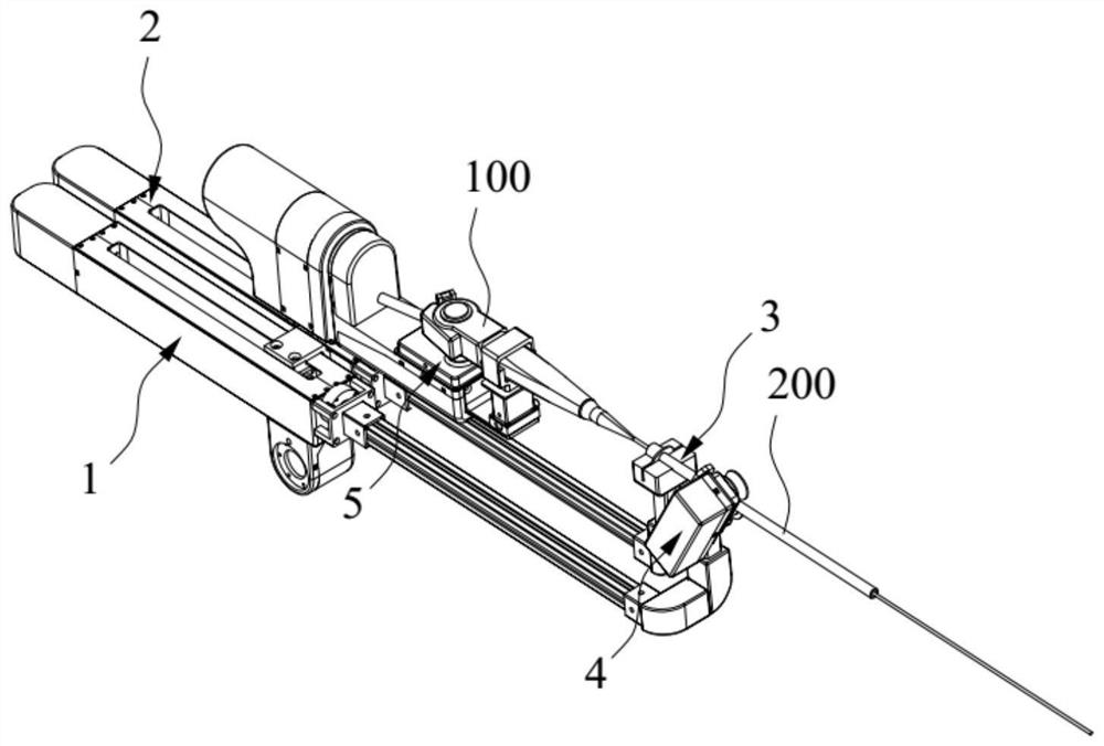
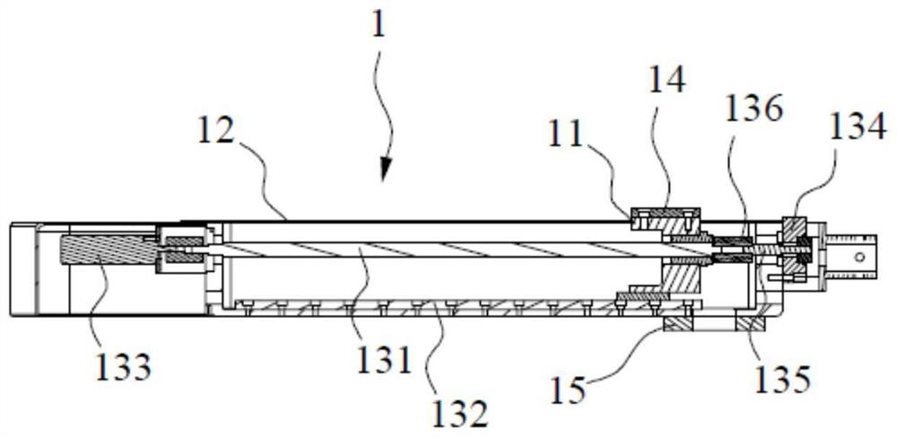
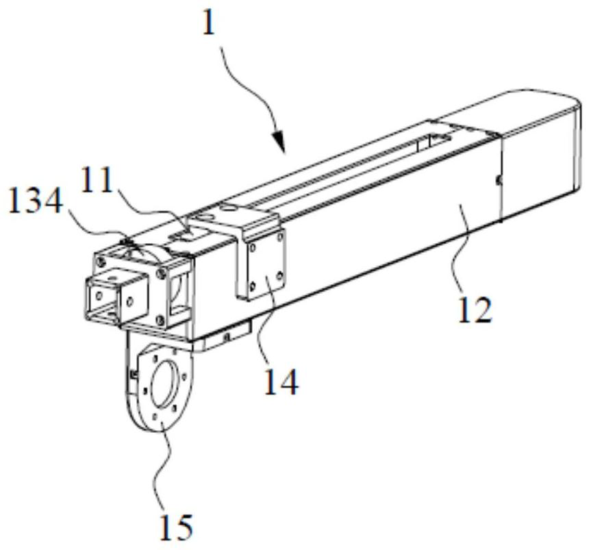
[0050] The present embodiment provides a tracheal intubation mechanism. as Figure 1-Figure 10 As shown, the endotracheal intubation mechanism comprises a first drive unit 1, a second drive unit 2, an installation assembly 3 and an auxiliary assembly 4. The first drive unit 1 includes a first output capable of moving in the first direction 11; The second drive unit 2 is connected to the first output member 11, the second drive unit 2 includes a second output member 21 and a frame 23, the second output member 21 can move in the second direction relative to the first output member 11, the second direction is parallel to the first direction, the frame 23 is connected to the second output member 21; Mounting assembly 3 includes a mounting bracket connecting rod 31 and a mounting bracket 32, the mounting bracket connecting rod 31 extends in the second direction, and one end of the mounting bracket connecting rod 31 is connected to one end of the second drive unit 2 along the second dire...

Embodiment 2

[0102] The present embodiment provides a tracheal intubation mechanism and a tracheal intubation robot, and compared with Example I, the structure provided in the present embodiment is substantially the same as that of Example I, only the structural settings of the auxiliary component 4 are different, and the present embodiment will no longer repeat the same structure as Example I.

[0103] As can be seen from the description above, the adapter 46 is the same structure as the removable cover 53, shell-like. as Figure 11 and Figure 12 As shown, in the present embodiment, the adjustment member 47 is disposed inside the adapter member 46, and can slide in a third direction. Adjuster 47 is provided with a spring 410 on one side opposite the first roller 43. One end of the spring 410 is connected to the adjuster 47, the other end of the spring 410 is connected to the inner wall of the adapter 46. When the spring 410 is in a natural state, the contact between the first roller 43 and the...


PUM


Abstract

The invention relates to the technical field of medical instruments, and discloses a tracheal intubation mechanism and a tracheal intubation robot. The tracheal intubation mechanism comprises a first driving unit used for driving a second output unit to move in the first direction; the second driving unit comprises a second output part and a mirror bracket, the second output part can relatively move in the second direction, and the mirror bracket is connected to the second output part; the mounting assembly comprises a mounting frame connecting rod and a mounting frame, one end of the mounting frame connecting rod is connected to the second driving unit, and the mounting frame is vertically connected to the other end of the mounting frame connecting rod; the auxiliary assembly comprises a roller connecting rod and a roller frame, one end of the roller connecting rod is connected to the first driving unit, the other end of the roller connecting rod is connected to the roller frame, and a first roller and a second roller with parallel rotating axes are arranged on the roller frame; trachea intubation is achieved, medical workers do not need to make contact with a patient, the patient is rescued in time, the risk of cross infection is reduced, and the safety of the medical workers is guaranteed.

Description

Technical field [0001] The present invention relates to the technical field of medical devices, in particular to a tracheal intubation mechanism and a tracheal intubation robot. Background [0002] Endotracheal intubation is an important medical technique used in the treatment of patients, and endotracheal intubation refers to the treatment of artificial insertion of a catheter through the mouth or nasal cavity instead of the patient's breathing. There is currently no specialized intubation equipment, and the insertion of the endotrachea is done manually by a doctor with the assistance of a bronchoscope. The intubation sleeve is located on the distal end of the bronchoscope, and the doctor needs to hold the handle of the bronchoscope in one hand, so that the distal end of the bronchoscope is forward or rotated, while the other hand is forward to give or rotate the intubation so that the tube is inserted along the catheter until the tube reaches the desired position. In the proces...

Claims


Application Information

Patent Timeline
Patent Type & Authority Applications(China)
IPC IPC(8): A61M16/04A61B34/30
CPCA61M16/04A61B34/30A61B34/70A61B2034/303
Inventor 胡晓旻赵建厂王佳童
Owner 胡晓旻
Why Eureka
Try Eureka