Machining device for motor output shaft

A processing device and output shaft technology, which is applied to grinding drive devices, metal processing equipment, grinding/polishing safety devices, etc., to facilitate collection and processing and ensure cleaning effects.

Pending Publication Date: 2022-06-07
钱歌
View PDF0 Cites 0 Cited by
  • Summary
  • Abstract
  • Description
  • Claims
  • Application Information

AI Technical Summary

Problems solved by technology

[0003] The output shaft of the motor needs to be polished during the production process, and there will be a lot of waste debris on the polished output shaft, which needs to be cleaned, but the existing cleaning equipment usually accumulates waste debris after cleaning it. In the cleaning area, this leads to a cleaning effect of the subsequent output shaft

Method used


Image

  • Machining device for motor output shaft
  • Machining device for motor output shaft
  • Machining device for motor output shaft

Examples


Embodiment 1

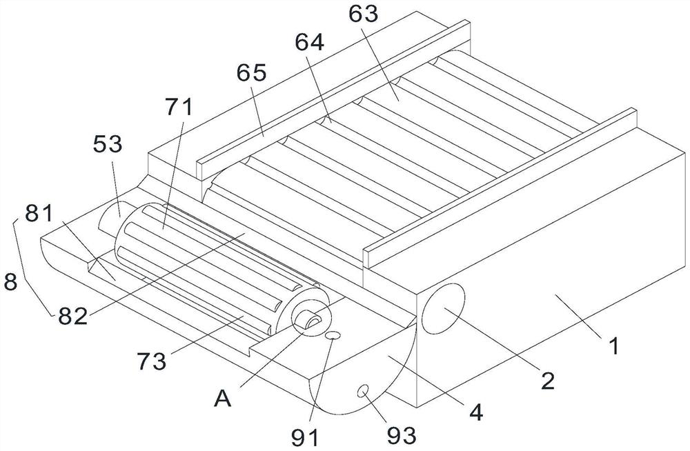
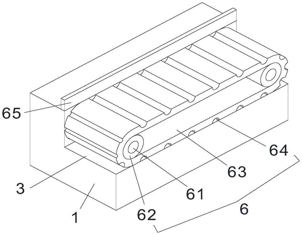
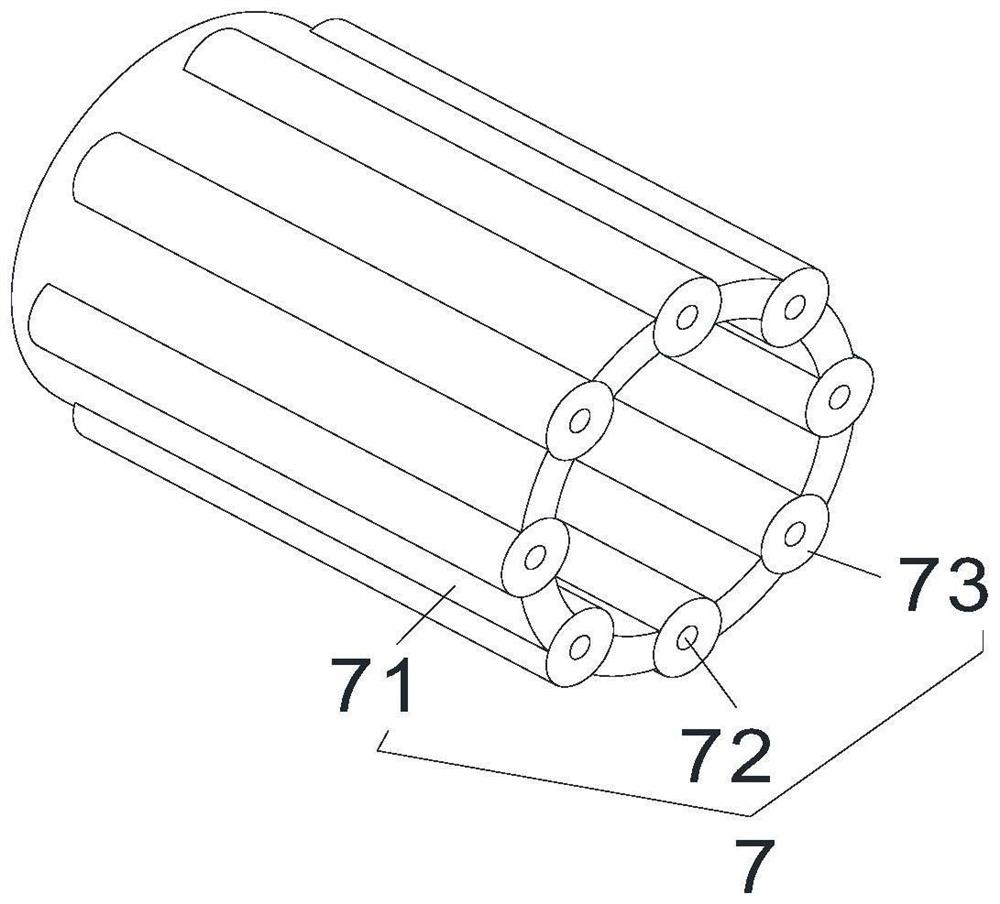
[0035] Example 1: as Figure 1-4 and Figure 7-8 As shown, a processing device for motor output shaft includes a body 1, a feeding motor 2, a placement processing mechanism 4, a driving mechanism 5 and a transmission mechanism 6, and a processing mechanism 7 is arranged inside the feeding motor 2, and the upper The feeding motor 2 is provided with an unloading mechanism 8, and the transmission mechanism 6 is used to cooperate with the feeding motor 2 to transport the output shaft of the motor to be processed to the placement and processing mechanism 4 for processing and cleaning. When the motor output shaft is cleaned, the cleaned waste is cleaned to one side, and the cleaning device 10 is used to cooperate with the processing mechanism 7. The cleaning device 10 will be synchronously driven to operate when the processing mechanism 7 is in operation, thereby The wastes in the placement and treatment mechanism 4 are accumulated to one side of the placement and treatment mechani...

Embodiment 2

[0042] Embodiment 2: on the basis of Embodiment 1, refer to Figure 5-Figure 6 , the inside of the placement processing mechanism 4 is also provided with an injection and discharge mechanism 9, the injection and drainage mechanism 9 includes a liquid injection port 91, the liquid injection port 91 is a hole of a circular truncated structure, and the liquid injection port 91 is opened on the right side of the top wall surface of the placement processing mechanism 4 On the side, the injection and discharge mechanism 9 also includes a liquid inlet groove 92, the liquid inlet groove 92 is a cylindrical inclined groove, the liquid inlet groove 92 is opened in the interior of the placement processing mechanism 4, and the bottom of the liquid inlet groove 92 is connected with the processing groove 41. The top of the liquid inlet tank 92 is communicated with the liquid injection port 91. The right side wall surface of the placement processing mechanism 4 is provided with a liquid disch...


PUM


Abstract

The invention relates to the field of motors, and discloses a motor output shaft machining device which comprises a machine body, a feeding motor, a placement treatment mechanism, a mounting groove and a placement treatment mechanism, a machining groove is formed in the top wall face of the placement treatment mechanism, a driving mechanism is arranged at the top of the feeding motor, and a conveying mechanism is arranged in the machine body; a machining treatment mechanism is arranged in the feeding motor, a cleaning device is arranged in the machining treatment mechanism, and the conveying mechanism is used for being matched with the feeding motor to convey the to-be-treated motor output shaft into the placement treatment mechanism. According to the machining device for the motor output shaft, the cleaning device is used for being matched with the machining treatment mechanism, and the cleaning device can be synchronously driven to operate when the machining treatment mechanism operates, so that sweeps in the placement treatment mechanism are accumulated to one side in the placement treatment mechanism through the cleaning device; and the cleaning effect of the machining mechanism on the motor output shaft is ensured.

Description

technical field [0001] The invention relates to the field of motors, in particular to a processing device for an output shaft of a motor. Background technique [0002] Motor, commonly known as motor, refers to an electromagnetic device that realizes the conversion or transmission of electrical energy according to the law of electromagnetic induction. The motor is represented by the letter M in the circuit. Its main function is to generate driving torque. The power source, the generator is represented by the letter G in the circuit. Its main function is to convert mechanical energy into electrical energy. The output shaft of the motor is the power output point of the motor. [0003] The output shaft of the motor needs to be ground during the production process, and a large amount of waste will remain on the output shaft after grinding, which needs to be cleaned, but the existing cleaning equipment usually accumulates waste after cleaning it. In the cleaning area, this leads ...

Claims


Application Information

Patent Timeline
Patent Type & Authority Applications(China)
IPC IPC(8): B24B5/04B24B41/00B24B41/02B24B47/12B24B55/06
CPCB24B5/04B24B41/005B24B55/06B24B41/00B24B41/02B24B47/12Y02P70/10
Inventor 钱歌
Owner 钱歌
Why Eureka
Try Eureka