Lifting device for pipeline installation construction

A technology of pipeline installation and lifting platform, applied in the direction of lifting device, etc., can solve problems such as difficult handling, and achieve the effect of convenient transportation and storage

Active Publication Date: 2022-06-07
中建五局安装工程有限公司
View PDF6 Cites 4 Cited by
  • Summary
  • Abstract
  • Description
  • Claims
  • Application Information

AI Technical Summary

Problems solved by technology

[0004] In view of the related technologies mentioned above, the inventor believes that in the process of installing the assembled ventilation system components to the ceiling, if the overhead crane is used for hoisting, the beams of the overhead crane will easily collide with the pipelines on the ceiling. The lifting device needs to move the ventilation system components to the lifting platform of the lifting device before lifting. Due to the limitation of the scissor structure itself, the lifting platform is higher than the ground, and it is difficult to carry

Method used


Image

  • Lifting device for pipeline installation construction
  • Lifting device for pipeline installation construction
  • Lifting device for pipeline installation construction

Examples


Embodiment 1

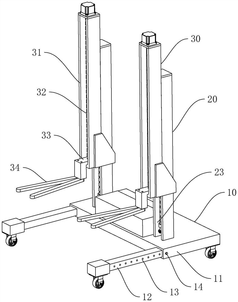
[0037] Embodiment 1, the embodiment of the present application discloses a lifting device for pipeline installation and construction, refer to figure 1 , including a mobile platform 10, on which a lifting assembly for lifting the ventilation system assembly is arranged.

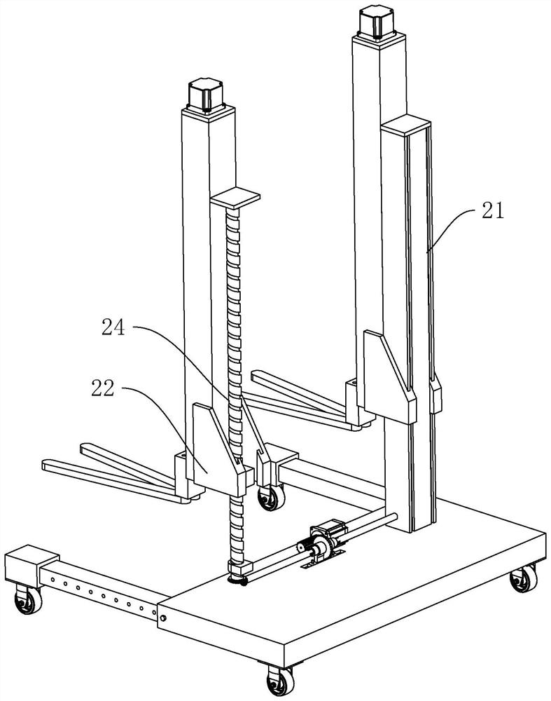
[0038]There are two sets of lift assemblies, each set of lift assemblies includes a first lift unit 20 and a second lift unit 30, the first lift unit 20 includes a first column 21 fixed on the mobile platform 10, and the first column 21 is provided with The first lifting platform 22 and the first driving mechanism that drives the first lifting platform 22 to move relative to the first column 21, the second lifting unit 30 includes a second column 31 fixed on the first lifting platform 22, and the second column 31 is provided There is a second lifting platform and a second driving mechanism that drives the second lifting platform to slide relative to the second column 31. When in use, the second lifting platfo...

Embodiment 2

[0049] Example 2, refer to Image 6 The difference between this embodiment and Embodiment 1 is that the base 11 is provided with a rotating shaft, the support arm 12 is hinged with the rotating shaft, the rotating shaft is arranged vertically, and in the folded state, the support arm 12 is located below the second lifting platform. When the support arm 12 is in the retracted state, it can support the fork 34, and when stored for a long time, the shearing force of the fork 34 on the second driving mechanism can be reduced by its own weight.

Embodiment 3

[0050] Example 3, refer to Figure 7 and Figure 8 The difference between this embodiment and Embodiment 2 is that the rotating shaft is arranged horizontally, and in the folded state, the support arm 12 rotates to a state parallel to the first column 21 . The base 11 is provided with a first running wheel 15 and a transition wheel 17, and the support arm 12 is provided with a second running wheel 16. In the folded state, the base 11 can rotate with the transition wheel 17 as a fulcrum to configure the lifting device in a standing posture and a lying state. In the posture state, the fork 34 needs to be removed before switching to the lying posture state; in the standing posture state, the first running wheel 15 and the transition wheel 17 are carried, and in the lying posture state, the second running wheel 16 and the transition wheel are carried.

[0051] When the support arm 12 is in the folded state, the whole lifting device can be pushed on the ground in a lying position ...


PUM


Abstract

The invention relates to a lifting device for pipeline installation construction, and belongs to the field of prefabricated pipeline installation construction, the lifting device comprises a moving platform, the moving platform is provided with a lifting assembly, and the lifting assembly comprises a first lifting unit and a second lifting unit; the first lifting unit comprises a first stand column fixed to the movable platform, a first lifting platform and a first driving mechanism for driving the first lifting platform to move relative to the first stand column are arranged on the first stand column, and the second lifting unit comprises a second stand column fixed to the first lifting platform. A second lifting platform and a second driving mechanism for driving the second lifting platform to slide relative to the second stand column are arranged on the second stand column, a receding groove is formed in the position, below the second lifting unit, of the movable platform, and the second lifting platform comprises a supporting plate. The ventilation system assembly has the effect that the ventilation system assembly can be conveniently hoisted indoors.

Description

technical field [0001] The present application relates to the field of installation and construction of prefabricated pipelines, and in particular, to a lifting device for installation and construction of pipelines. Background technique [0002] During the construction of the ventilation system, it is necessary to install ventilation ducts and terminal devices for adjusting the air supply and tracking load changes to maintain the room temperature. The ventilation ducts and the terminal devices need to be supported by support components. [0003] In the traditional construction method, the ventilation duct components and support components are cut and processed on the construction site. In order to improve the construction efficiency and shorten the construction period, the ventilation ducts and the connecting parts of the ventilation ducts are prefabricated in the processing workshop. The construction method of transporting it to the construction site for assembly, so that t...

Claims


Application Information

Patent Timeline
Patent Type & Authority Applications(China)
IPC IPC(8): B66F9/06B66F9/075B66F9/12B66F9/14
CPCB66F9/06B66F9/075B66F9/12B66F9/144
Inventor 徐延光刘勇唐彪廖传飞孟艺多李佳胡坤龙许璐
Owner 中建五局安装工程有限公司
Why Eureka
Try Eureka