Wind power supply device of container positioning system
A positioning system and wind power supply technology, applied in the installation/supporting configuration of wind power generators, wind power generation, wind power generators, etc., can solve the problems of blade transformation, inability to fully utilize natural resources, and inability to fully utilize wind power, etc., to achieve The power generation state is stable, the battery protection effect is good, and the installation is stable.
- Summary
- Abstract
- Description
- Claims
- Application Information
AI Technical Summary
Problems solved by technology
Method used
Image
Examples
Embodiment 1
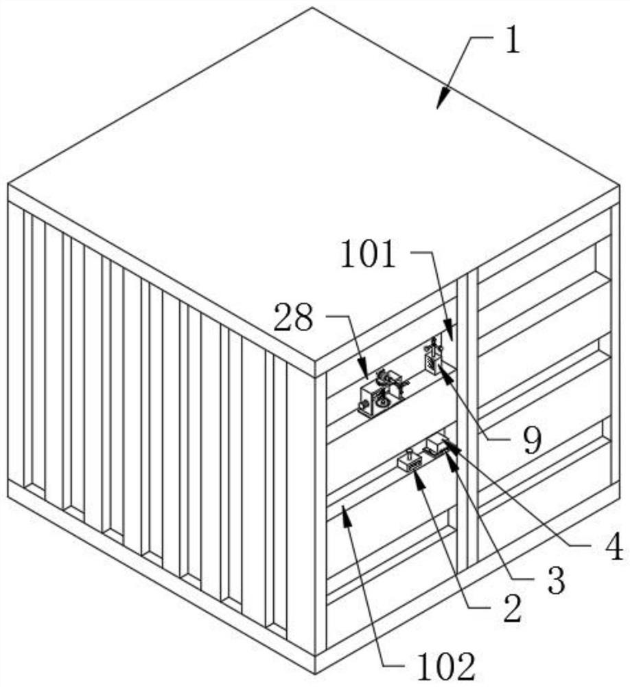
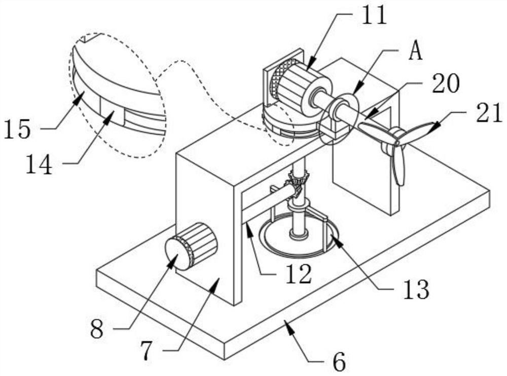
[0031] like Figure 1-8 As shown, the wind power supply device of the container positioning system proposed by the present invention includes a container body 1 and a groove a101 and a groove b102 opened on the side of the container 1. The groove b102 is provided with a positioner 2 and a bottom plate a3, and the groove a101 passes through the groove a101. The bottom plate b6 is connected with a U-shaped mounting plate 7, the upper end of the bottom plate b6 is rotatably connected with a rotating column 27 that penetrates through the U-shaped mounting plate 7, the upper end of the rotating column 27 is connected with a support plate 16, and the upper end of the support plate 16 passes through the generator mounting plate 17. The generator 11 is installed, the upper end of the support plate 16 is provided with an installation groove 18, the generator 11 is installed in the installation groove 18, the lower end of the support plate 16 is connected with two symmetrically arranged ...
Embodiment 2
[0034] like Figure 4 As shown in the figure, the wind power supply device for the container positioning system proposed by the present invention, compared with the first embodiment, this embodiment further includes: a plurality of heat dissipation holes 26 are opened on both sides of the U-shaped support plate 22, and the upper end of the battery 23 is connected with a The top block 24, the upper end of the top block 24 is provided with a positioning groove 25, combined with Image 6 , the inner wall of the upper end of the protective cover 401 is connected with a positioning rod 404 that matches the positioning groove 25. When the protective cover 401 covers the outside of the battery 23, the positioning rod 404 will be inserted into the positioning groove 25, so that the battery 23 can be positioned. Therefore, the disassembly and assembly of the battery 23 is very convenient, and the stabilization effect of the battery 23 is also very good, and it is not easy to loosen whe...
Embodiment 3
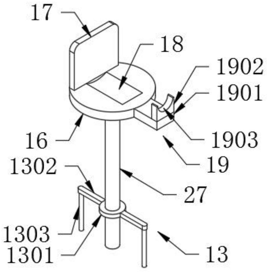
[0036] like image 3 As shown in the figure, the wind power supply device for the container positioning system proposed by the present invention, compared with the first or second embodiment, the present embodiment further includes: a support mechanism 13 is provided below the rotating column 27 , and the support mechanism 13 includes a support mechanism 13 sleeved on the rotating column 27 . The support ring 1301 on the outer side of the column 27, the outer surface of the support ring 1301 is connected with two symmetrically arranged connecting rods 1302; the lower ends of the two connecting rods 1302 are connected with sliding rods 1303 on the side away from each other, and the two sliding rods 1303 are It plays a supporting and stable role for the rotating column 27, so that the rotating column 27 can play a stable supporting role on the support plate 16, and the rotating column 27 can also be very stable when the direction changes; The annular chute a on which the two sli...
PUM
 Abstract
Description
Claims
Application Information
 - R&D
- Intellectual Property
- Life Sciences
- Materials
- Tech Scout
- Unparalleled Data Quality
- Higher Quality Content
- 60% Fewer Hallucinations
Browse by: Latest US Patents, China's latest patents, Technical Efficacy Thesaurus, Application Domain, Technology Topic, Popular Technical Reports.
© 2025 PatSnap. All rights reserved.Legal|Privacy policy|Modern Slavery Act Transparency Statement|Sitemap|About US| Contact US: help@patsnap.com


