Combined roller structure, roller, high-end bearing and high-end equipment

A roller and bearing technology, used in high-end equipment, rollers, combined roller structures, and high-end bearings, can solve problems such as poor self-cleaning performance, aggravated grinding, and shortened life, to reduce weight, increase service life, increase effect on overall lifespan

Pending Publication Date: 2022-06-07
长春电子科技学院
View PDF14 Cites 0 Cited by
  • Summary
  • Abstract
  • Description
  • Claims
  • Application Information

AI Technical Summary

Problems solved by technology

[0009] Technical problem A. The waste debris generated by the wear of the existing bearing roller or roller cavity will further aggravate the grinding, resulting in a rapid decrease in life and precision
[0010] Technical problem B. Poor self-cleaning performance

Method used


Image

  • Combined roller structure, roller, high-end bearing and high-end equipment
  • Combined roller structure, roller, high-end bearing and high-end equipment
  • Combined roller structure, roller, high-end bearing and high-end equipment

Examples


Embodiment 1

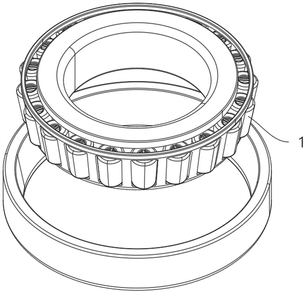
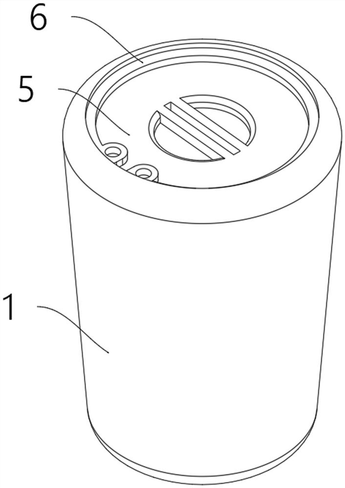
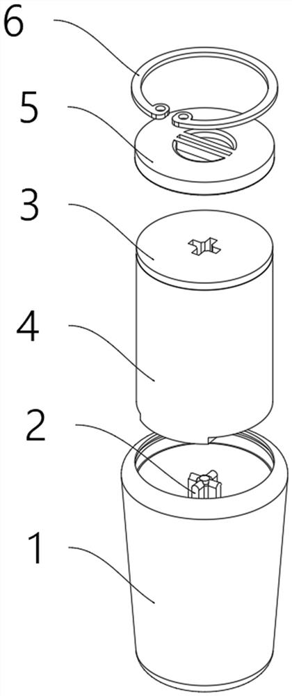
[0043] like Figure 1-3 As shown, the combined roller structure, compared with the prior art, is unique in that: it is used as a constituent part of the bearing roller; it has a roller shell 1, a cross column 2, a combined piece 3, a clip 5 and a clip spring 6 The main body of the roller shell 1 is a tapered trapezoidal shell structure, and the top inner side of the roller shell 1 is a hollow structure; the bottom side of the roller shell 1 is provided with two inclined grooves 101, and the two inclined grooves 101 are symmetrical; The interval between the bottom end openings of the two groups of inclined grooves 101 is greater than the interval between the top end openings of the two groups of inclined grooves 101;

[0044] The inner side of the roller shell 1 is provided with a shoulder structure, and the upper position of the shoulder structure is provided with a spring groove 102;

[0045] The cross column 2 is integrally arranged in the middle of the inner side of the ro...

Embodiment 2

[0052] like Figure 8 As shown in the figure, the cylindrical casing 4 is unique compared with the prior art in that it is designed to fit the roller shell 1 and the rolling diamond column 301 described in Embodiment 1, and the middle of the cylindrical casing 4 runs through the upper and lower ends. A diamond-shaped groove 402 is opened.

[0053] Embodiment 2-1, based on the technical solution of Embodiment 2, a further optional technical solution: the material of the columnar container 4 is a foamed sponge with a shrinkage rate exceeding five times; the bottom of the columnar container 4 is opened There is an oil channel 401 .

[0054] Embodiment 2-2, based on the technical solution of Embodiment 2, a further optional technical solution: the oil channel 401 is opened around, and both ends of the oil channel are connected to the top ends of the chute 101 .

[0055] Embodiment 2-3, based on the technical solution of Embodiment 2, a further optional technical solution: the cyli...

Embodiment 3

[0057] like image 3 The bottom of the combination sheet 3 is provided with a docking slot 302 in the middle of the bottom of the diamond-shaped column, which is slidably arranged outside the docking column 2. The roller shell 1 described in Example 1 is designed to include a diamond-shaped column 301 and a butt groove 302;

[0058] The shapes of the rhombus column 301 and the butt groove 302 are kept the same;

[0059] The diamond-shaped column 301 is arranged in the middle of the bottom of the composite sheet 3, and the outer surface of the diamond-shaped column 301 is a smooth surface;

[0060] The lengths of the upper and lower corners of the diamond-shaped column 301 are the same;

[0061] like Figure 7 As shown, a diamond-shaped column 301 is arranged in the middle of the bottom of the composite sheet 3, and a docking slot 302 is arranged in the middle of the bottom of the diamond-shaped column 301;

[0062] The diamond-shaped column 301 can cooperate with the docki...


PUM


Abstract

The invention relates to the technical field of high-end equipment. The combined pin roller structure is used as a component of a bearing pin roller and is composed of a pin roller shell, a cross-shaped column, a combined piece, a clamping piece and a clamping spring. The pin roller is used for the cylindrical roller bearing, serves as a bearing component and comprises the combined pin roller structure A1 and a columnar containing sleeve. The high-end bearing is provided with a pin roller and is composed of an outer ring, an inner ring, a supporting frame and a pin roller. The high-end equipment is provided with the bearing, and the bearing is the high-end bearing. The bearing is suitable for an application environment with small load and high precision requirement, has a quick maintenance and disassembly function, reduces the weight of the bearing, reduces the manufacturing cost, prolongs the service life, can well adapt to a shaft piece, and provides a radial bearing function.

Description

technical field [0001] The invention relates to the technical field of high-end equipment, in particular to a combined roller structure, a roller, a high-end bearing and high-end equipment. Background technique [0002] Roller bearing is a kind of rolling bearing. It mainly rotates through the circular contact of the roller, and can bear the radial force of large force. During the rotation process, the roller will rotate by itself. [0003] High-end equipment generally refers to high-precision, high-speed, high-weight load or high-tech difficult, industrial equipment, and important industrial products that are difficult for most countries or enterprises to produce. [0004] The R&D and production of various high-end equipment has a huge positive impact on the development of economy, industry, military, science and technology, and culture. The development of high-end equipment and high-end bearings is an important development strategy for the development of my country's indus...

Claims


Application Information

Patent Timeline
Patent Type & Authority Applications(China)
IPC IPC(8): F16C19/36F16C33/36F16C33/66
CPCF16C19/364F16C33/366F16C33/6659F16C33/6681
Inventor 吴翠红赵晶苏东楠王蕾
Owner 长春电子科技学院
Why Eureka
Try Eureka