Eureka AIR delivers breakthrough ideas for toughest innovation challenges, trusted by R&D personnel around the world.

Fuel cell stack cathode humidity control system and control method thereof

A fuel cell stack and humidity control system technology, which is applied in the direction of fuel cells, circuits, electrical components, etc., can solve the problems of blocked gas transmission, failure to meet the humidity requirements of the fuel cell system, and the decrease of the humidifier dry test outlet, etc., to achieve The effect of ensuring the service life

Pending Publication Date: 2022-06-07
SHANGHAI CHONGSU ENERGY TECH CO LTD
View PDF0 Cites 2 Cited by
  • Summary
  • Abstract
  • Description
  • Claims
  • Application Information

AI Technical Summary

Problems solved by technology

[0003] Humidity is very important to fuel cells. Improper control will seriously affect the performance and life of fuel cells. Too low air intake humidity will easily cause the membrane electrode to dry out, thereby reducing the conductivity of the fuel cell. Excessive intake air humidity will easily cause water flooding. The gas transfer is blocked, and the air side of the current fuel cell is basically humidified by an external humidifier to increase the air humidity
[0004] With the increase of the operating temperature of the fuel cell system, especially during high-power operation, the inlet temperature of the dry side of the humidifier (equal to the inlet temperature of the stack cooling water) and the inlet temperature of the wet side of the humidifier (equal to the outlet temperature of the stack cooling water Relatively high), the relative humidity decreases, resulting in a decrease in the efficiency of the humidifier, and a decrease in the relative humidity of the dry outlet of the humidifier, which cannot meet the humidity requirements of the fuel cell system

Method used


Image

  • Fuel cell stack cathode humidity control system and control method thereof
  • Fuel cell stack cathode humidity control system and control method thereof

Examples


Embodiment Construction

[0031] The specific embodiments of the present invention will be further described in detail below with reference to the accompanying drawings. These embodiments are only used to illustrate the present invention, but not to limit the present invention.

[0032] In the description of the present invention, it should be noted that the terms "installed", "connected" and "connected" should be understood in a broad sense, unless otherwise expressly specified and limited, for example, it may be a fixed connection or a detachable connection Connection, or integral connection; can be mechanical connection, can also be electrical connection; can be directly connected, can also be indirectly connected through an intermediate medium, can be internal communication between two elements. For those of ordinary skill in the art, the specific meanings of the above terms in the present invention can be understood according to specific situations.

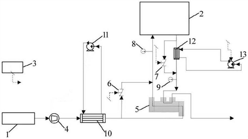
[0033] like figure 1 As shown, a fuel cell s...


PUM


Abstract

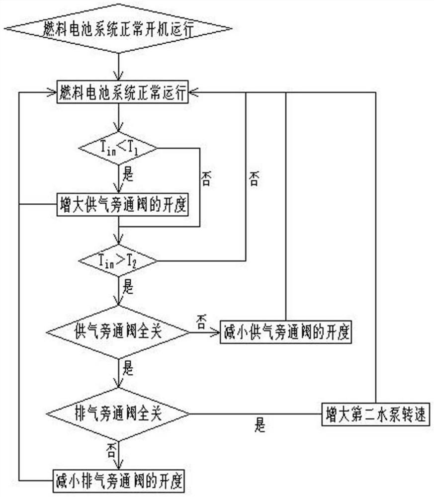
The invention discloses a fuel cell stack cathode humidity control system and a control method thereof.The fuel cell stack cathode humidity control system comprises an air source, a stack and a controller, and an air compressor, a first radiator and a humidifier are sequentially arranged between the air source and a stack cathode inlet in the air flow direction; an air supply bypass valve is arranged between the air outlet of the first radiator and the cathode inlet of the electric pile, a second radiator and an exhaust bypass valve which are connected in parallel are arranged between the cathode outlet of the electric pile and the wet side inlet of the humidifier, and the wet side outlet of the humidifier is connected with the outside atmosphere. The controller is used for analyzing the air temperature at the cathode inlet of the electric pile, and the output end of the controller is connected with the air supply bypass valve, the exhaust bypass valve and the second radiator. The air temperature and humidity at the cathode inlet of the electric pile are adjusted by adjusting the air temperature at the wet side inlet of the humidifier, so that the humidity requirement of the electric pile is met.

Description

technical field [0001] The invention belongs to the technical field of fuel cell humidity control, and in particular relates to a fuel cell stack cathode humidity control system and a control method thereof. Background technique [0002] The fuel of the fuel cell is hydrogen, the combustion gas is oxygen, and the product is clean water. The fuel cell itself does not produce carbon monoxide and carbon dioxide, nor does it emit sulfur and particulates. Therefore, hydrogen fuel cell vehicles are truly zero-emission, zero-emission. polluted car. [0003] Humidity is very important to fuel cells. Improper control will seriously affect the performance and life of fuel cells. Too low intake air humidity will easily lead to drying of membrane electrodes, and then the conductivity of fuel cells will decrease. The gas transfer is blocked, and the air side of the current fuel cell is basically humidified by an external humidifier to increase the air humidity. [0004] As the operatin...

Claims


Application Information

Patent Timeline
IPC IPC(8): H01M8/04119H01M8/04828
CPCH01M8/04126H01M8/04828Y02E60/50
Inventor 蒋恩杰余慧峰程准王佳元
Owner SHANGHAI CHONGSU ENERGY TECH CO LTD
Why Eureka
Eureka Blog
Learn More