Paint spraying device used for valve machining and not prone to paint leakage
A technology of paint leakage and valves, which is applied in the direction of spraying devices, spray booths, grinding drive devices, etc., can solve the problems of harming the human body, paint leakage, metal burrs affecting the use, etc., and achieve the effect of reducing contact and ensuring the safety of personnel
- Summary
- Abstract
- Description
- Claims
- Application Information
AI Technical Summary
Problems solved by technology
Method used
Image
Examples
Embodiment 1
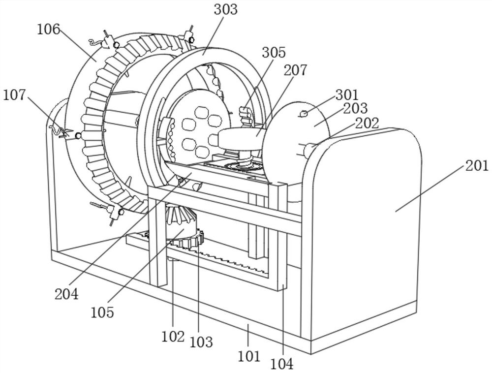
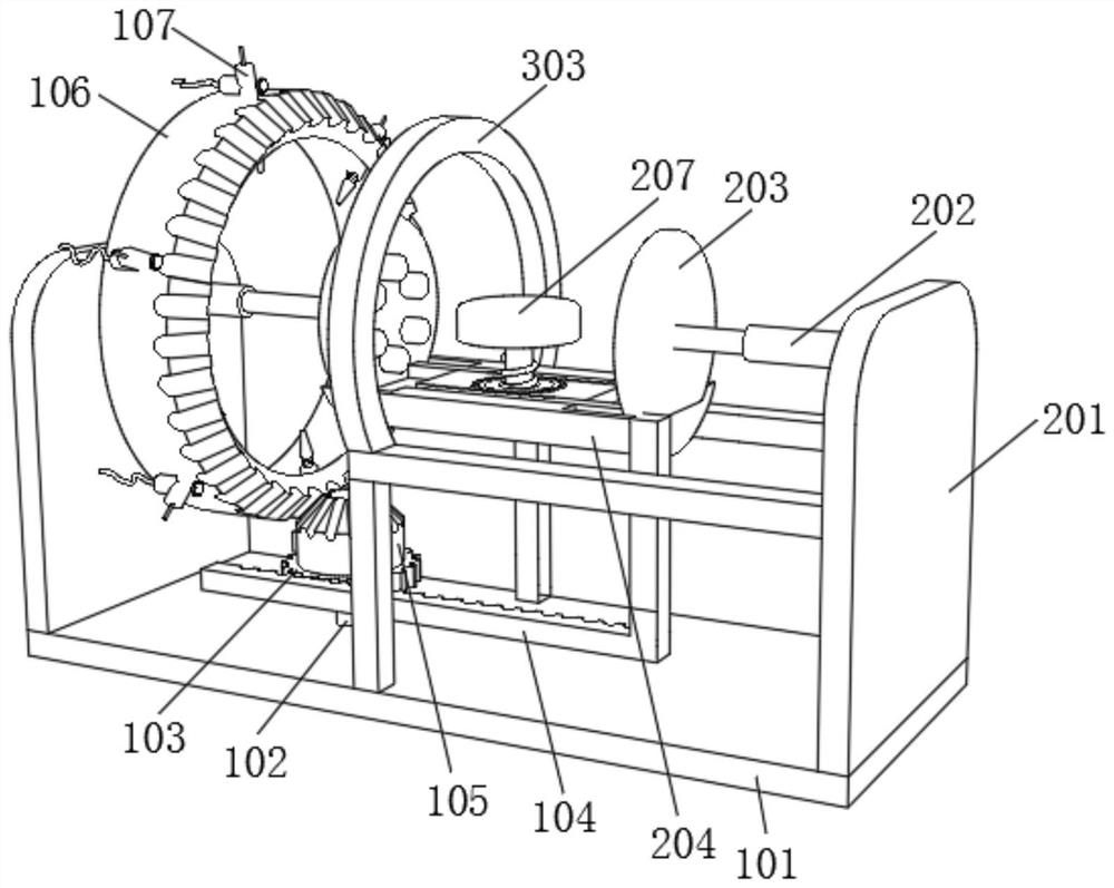
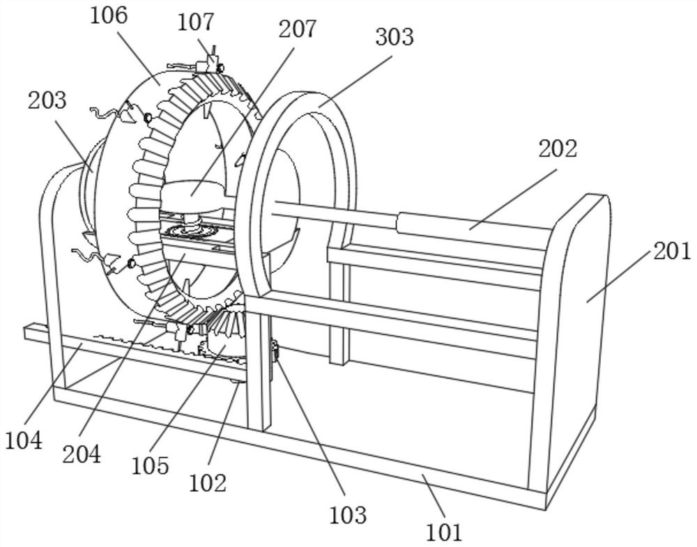
[0035] see Figure 1 to Figure 4 , a paint spraying device for valve processing that is not easy to leak paint, comprising a bottom plate 101, the top of the bottom plate 101 is fixedly connected with a strut 102, and the strut 102 is used to fix the position of the transmission gear 103 and the conical wheel 105; the top of the strut 102 is fixedly connected with a The transmission gear 103, the rotation of the transmission gear 103 drives the conical wheel 105 to rotate;
[0036] The outer side of the transmission gear 103 is provided with a transmission rack 104, the shape of the transmission rack 104 is L-shape, the transmission rack 104 meshes with the transmission gear 103, and the transmission rack 104 can make the transmission gear 103 rotate under the driving of the clamping device; The top of the transmission gear 103 is fixedly connected with a conical wheel 105, the size of the conical wheel 105 is matched with the runner 106, and the rotation of the conical wheel ...
Embodiment 2
[0039] see Figure 5 to Figure 8 , a paint spraying device for valve processing that is not easy to leak paint, further comprising a side plate 201, the back of the side plate 201 is fixedly connected with a telescopic rod 202, and the number of the telescopic rod 202 is two groups, which are respectively connected with the two plywoods 203 fixedly connected, The telescopic rod 202 can make the clamping device reciprocate;
[0040] One end of the telescopic rod 202 away from the side plate 201 is fixedly connected with a splint 203. There are a certain number of cylinders on the splint 203. The number and size of the cylinders fit the size of the valve. The cylinder on the valve can be embedded in the through hole on the valve, so as to fix the valve and not easy to shake;
[0041] The bottom of the splint 203 is plugged with a limit block 204 , the limit block 204 defines the position and movement track of the splint 203 , the size of the groove on the limit block 204 is mat...
Embodiment 3
[0045] see Figure 9 to Figure 11 , a paint spraying device for valve processing that is not easy to leak paint, the front of the splint 203 is fixedly connected with a sensor 301, and the sensor 301 transmits signals; The friction device is moved; the top of the receiver 302 is fixedly connected with a limit ring 303, and the limit ring 303 defines the position of the extrusion rod 304;
[0046] The inner side of the limit ring 303 is provided with an extrusion rod 304, and the extrusion rod 304 pushes the friction block 305 to move, so that the friction block 305 is extended inward or retracted outward; The number of blocks 305 is two, each friction block 305 is composed of a fixed block and several friction rollers, and the friction block 305 fits the valve surface, so as to clean the metal burrs on the valve surface.
[0047] Working process and principle: please refer to Figure 1 to Figure 11 , This paint spraying device for valve processing that is not easy to leak pa...
PUM
 Abstract
Description
Claims
Application Information
 - R&D
- Intellectual Property
- Life Sciences
- Materials
- Tech Scout
- Unparalleled Data Quality
- Higher Quality Content
- 60% Fewer Hallucinations
Browse by: Latest US Patents, China's latest patents, Technical Efficacy Thesaurus, Application Domain, Technology Topic, Popular Technical Reports.
© 2025 PatSnap. All rights reserved.Legal|Privacy policy|Modern Slavery Act Transparency Statement|Sitemap|About US| Contact US: help@patsnap.com


