Electroplating device based on lead frame and electroplating method thereof

A lead frame and electroplating device technology, applied in electrodes, electrolysis components, electrolysis process, etc., can solve the problems of troublesome reclaiming operation, single use structure, unfavorable use, etc., and achieve convenient reclaiming operation, easy control, and increased effect. Effect

Pending Publication Date: 2022-06-21
泰兴市龙腾电子有限公司
View PDF0 Cites 0 Cited by
  • Summary
  • Abstract
  • Description
  • Claims
  • Application Information

AI Technical Summary

Problems solved by technology

[0003] The existing electroplating devices have certain disadvantages in use. First, when the lead frame is electroplating, the internal temperature cannot be conveniently controlled, the cathode position cannot be moved well, and the use structure is relatively simple, which is not conducive to People's use, in addition, the operation of retrieving materials during use is more troublesome, which brings certain adverse effects to people's use process. Therefore, we propose an electroplating device and its electroplating method based on lead frame

Method used


Image

  • Electroplating device based on lead frame and electroplating method thereof
  • Electroplating device based on lead frame and electroplating method thereof
  • Electroplating device based on lead frame and electroplating method thereof

Examples


Embodiment 1

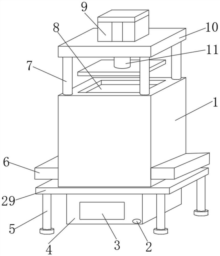
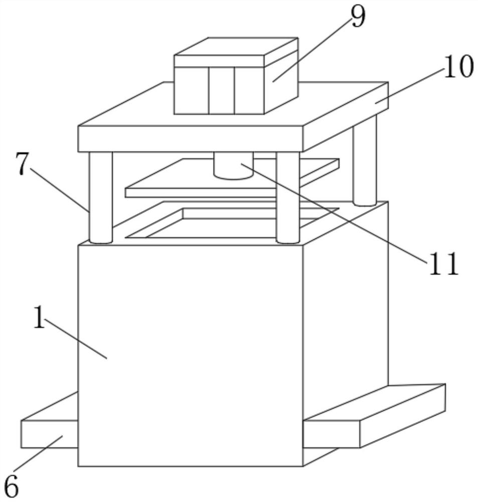
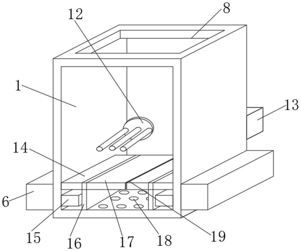
[0032] like Figure 1-6As shown, based on the electroplating device for lead frame, it includes a device main body 1, an installation support 29, a liquid outlet tank 4 and an electroplating function management platform. The front end of the liquid outlet box 4 is provided with an observation window 3 and a liquid outlet 2, the upper end of the device main body 1 is provided with a lifting column 7 at the four corners, the upper end of the lifting column 7 is equipped with a lifting plate 10, and the upper end of the device main body 1 is provided in the middle. There is an opening 8, and a foot 5 is mounted on the bottom of the mounting support 29.

[0033] Further, a seat plate 14 is installed inside the device main body 1 , a telescopic plate 17 is arranged on the inner side of the seat plate 14 , a sealing gasket 19 is fixedly connected to the side of the telescopic plate 17 , and a sealing box is fixedly installed at the bottom of the seat plate 14 16. A heater 15 is ins...

Embodiment 2

[0037] On the basis of Example 1, as Figure 1-6 As shown, based on the electroplating device for lead frame, it includes a device main body 1, an installation support 29, a liquid outlet tank 4 and an electroplating function management platform. The front end of the liquid outlet box 4 is provided with an observation window 3 and a liquid outlet 2, the upper end of the device main body 1 is provided with a lifting column 7 at the four corners, the upper end of the lifting column 7 is equipped with a lifting plate 10, and the upper end of the device main body 1 is provided in the middle. There is an opening 8, and a foot 5 is mounted on the bottom of the mounting support 29.

[0038] Further, a cylinder 9 is installed on the upper end of the lifting plate 10, a lifting rod 11 is arranged at the bottom of the cylinder 9, a positioning connecting seat 23 is installed at the bottom position of the lifting rod 11, and a material reclaiming seat 27 is installed at the bottom positi...

Embodiment 3

[0041] On the basis of Embodiment 1 and Embodiment 2, as Figure 1-6 As shown, based on the electroplating device for lead frame, it includes a device main body 1, an installation support 29, a liquid outlet tank 4 and an electroplating function management platform. The front end of the liquid outlet box 4 is provided with an observation window 3 and a liquid outlet 2, the upper end of the device main body 1 is provided with a lifting column 7 at the four corners, the upper end of the lifting column 7 is equipped with a lifting plate 10, and the upper end of the device main body 1 is provided in the middle. There are 8 openings.

[0042] Further, the electroplating function management platform is connected with a state monitoring module, the state monitoring module is connected with a PLC control unit, the PLC control unit is connected with a display module and a state control module, and the state monitoring module includes a temperature monitoring module, an electroplating m...


PUM


Abstract

The electroplating device comprises a device body, a mounting support, a liquid outlet box and an electroplating function management platform, the device body is located at the upper end of the mounting support, the liquid outlet box is located at the bottom of the mounting support, and an observation window and a liquid outlet are formed in the front end of the liquid outlet box; lifting columns are arranged at the four corners of the upper end of the device body, a lifting plate is installed at the upper ends of the lifting columns, and an opening is formed in the middle of the upper end of the device body. According to the electroplating device based on the lead frame and the electroplating method of the electroplating device, the temperature control type electroplating mechanism, the lifting material taking mechanism and the electroplating function management platform are arranged, electroplating operation can be conveniently and better carried out, the temperature control effect is achieved, the cathode part can move and stir, the electroplating effect is improved, efficiency is higher, and the electroplating effect is better. And material taking operation can be conveniently carried out, rapidness is achieved, function modules of the whole device can be conveniently controlled, and the device is simple and practical.

Description

technical field [0001] The present invention relates to the field of electroplating devices, in particular to a lead frame-based electroplating device and an electroplating method thereof. Background technique [0002] The electroplating device is a kind of supporting equipment for the surface of the part. Electroplating means that in the salt solution containing the metal to be plated, the base metal to be plated is used as the cathode. A surface processing method of depositing the surface to form a coating. With the continuous development of science and technology, people have higher and higher requirements for the manufacturing process of electroplating devices. [0003] The existing electroplating device has certain drawbacks in use. First, when the lead frame is electroplated, the internal temperature cannot be easily controlled, the cathode position cannot be moved well, and the use structure is relatively simple, which is not conducive to People's use, and the operat...

Claims


Application Information

Patent Timeline
Patent Type & Authority Applications(China)
IPC IPC(8): C25D17/00C25D17/12C25D21/12C25D21/10C25D21/02C25D7/00
CPCC25D17/00C25D17/12C25D21/12C25D21/10C25D21/02C25D7/00
Inventor 张伟陈虎陈惠
Owner 泰兴市龙腾电子有限公司
Why Eureka
Try Eureka