Hole shaft offset detection jig and operation method thereof

A technology for detecting jig and offset, applied in the field of parts detection, can solve the problems of chip damage, inaccurate measured offset, inability to accurately measure positioning holes and positioning shafts, etc., to achieve the effect of simple structure

Pending Publication Date: 2022-06-21
东莞利扬芯片测试有限公司
View PDF28 Cites 0 Cited by
  • Summary
  • Abstract
  • Description
  • Claims
  • Application Information

AI Technical Summary

Problems solved by technology

Frequent plugging and unplugging of positioning shafts and positioning holes is prone to wear and tear, but chip testing has extremely high requirements for chip positioning. For example, when the wear offset of the positioning hole exceeds 0.2mm, the positioning will be inaccurate and the chip will be damaged. Therefore, regular positioning is required. The holes are measured, and the feeding carrier with excessive wear of the positioning holes is scrapped.
[0003] At present, the wear amount of the positioning hole is generally measured by a plug gauge, but the positioning hole is matched with the positioning column of the shuttle car to achieve the purpose of positioning. The plug gauge can only measure whether the offset of the positioning hole exceeds the standard to judge whether the wear amount exceeds the standard. It is impossible to measure the combined offset of the positioning hole and the positioning shaft, which makes the measured offset inaccurate, and it is easy to cause the offset measurement of the positioning hole to pass, but the problem of chip damage still occurs during the test
Of course, other technical fields that use positioning shafts and or positioning holes are also prone to problems due to the inability to accurately measure the offset of the positioning holes and positioning shafts, and cannot correctly determine whether the offset of the positioning holes and positioning shafts meets the standards.

Method used


Image

  • Hole shaft offset detection jig and operation method thereof
  • Hole shaft offset detection jig and operation method thereof
  • Hole shaft offset detection jig and operation method thereof

Examples


Embodiment Construction

[0031] In order to describe in detail the technical content, structural features, and achieved effects of the present invention, detailed descriptions are given below with reference to the embodiments and the accompanying drawings.

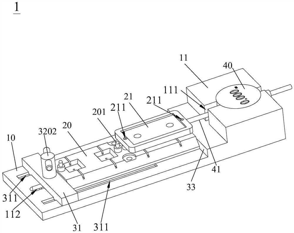
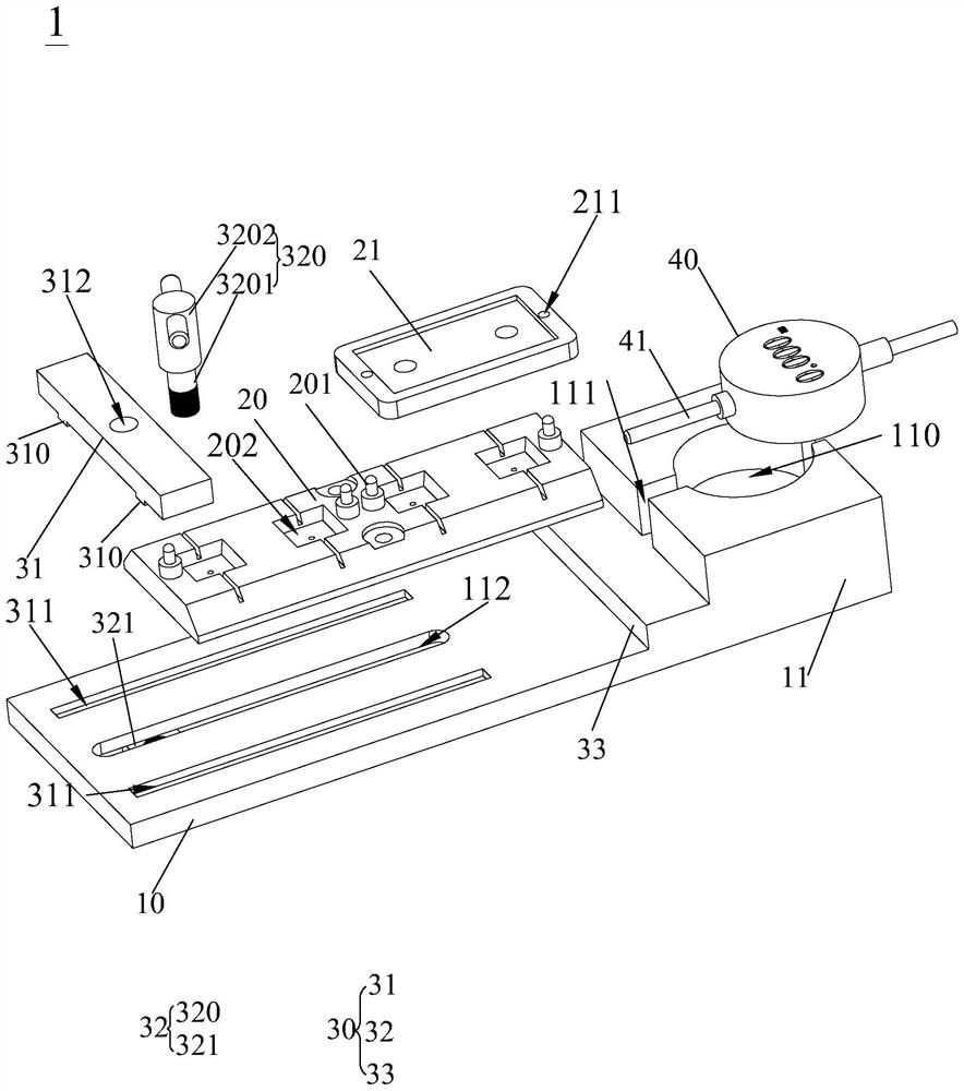
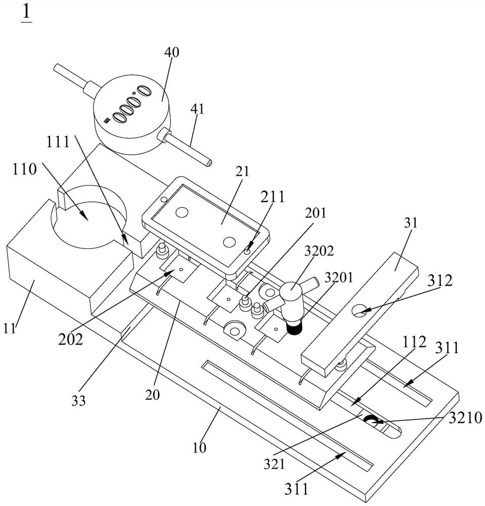
[0032] see Figure 1 to Figure 5 , the embodiment of the present invention discloses a hole axis offset detection fixture 1 , which includes a base 10 , a first substrate 20 , a second substrate 21 , a fixing device 30 and a detection device 40 .

[0033] The first substrate 20 is provided with one of the positioning shaft 201 and the positioning hole 211 , the second substrate 21 is provided with the other one of the positioning shaft 201 and the positioning hole 211 , and the second substrate 21 is assembled on the first substrate 20 When the positioning shaft 201 is inserted into the positioning hole 211 , the fixing device 30 is used to fix the first substrate 20 on the base 10 , and the detection device 40 is used to detect that the second su...


PUM


Abstract

The invention discloses a hole shaft offset detection jig and an operation method thereof, the hole shaft offset detection jig comprises a first substrate, a second substrate, a fixing device and a detection device, the first substrate is provided with any one of a positioning shaft and a positioning hole, the second substrate is provided with the other one of the positioning shaft and the positioning hole, and when the second substrate is assembled on the first substrate, the positioning shaft and the positioning hole are fixed on the fixing device. The positioning shaft is inserted into the positioning hole, the fixing device is used for fixing the first substrate on the base, and the detection device is used for detecting the maximum relative displacement between the first substrate and the second substrate when the second substrate is linearly pushed after the two substrates are assembled on the first substrate so as to detect the offset of the positioning hole and/or the positioning shaft. The hole shaft offset detection jig can accurately detect the offset of the positioning hole and/or the positioning shaft, so that whether the offset of the positioning hole and/or the positioning shaft meets the standard or not can be accurately judged, and the hole shaft offset detection jig is simple in structure.

Description

technical field [0001] The invention relates to the technical field of parts detection, in particular to a hole axis offset detection fixture and an operation method thereof. Background technique [0002] When testing the chip, it is necessary to move the chip to the accommodating groove of the shuttle. Generally, the chip is removed from the accommodating groove by the feeding carrier for testing, or the tested chip is put into the accommodating groove of the shuttle. In order to ensure the transfer During the process, the feeding carrier can accurately absorb the chips and ensure that the chips will not shift. A positioning shaft will be set on the shuttle car, and a positioning hole matched with the positioning shaft will be set on the feeding carrier to realize the positioning of the feeding carrier. Frequent plugging and unplugging of the positioning shaft and positioning hole is prone to wear and tear, but the chip test requires extremely high chip positioning. For exa...

Claims


Application Information

Patent Timeline
Patent Type & Authority Applications(China)
IPC IPC(8): G01B21/02G01B5/02G01B11/02G01B17/00
CPCG01B21/02G01B5/02G01B11/026G01B17/00
Inventor 李双成马海龙范传敏张永乐袁俊卢旭坤辜诗涛
Owner 东莞利扬芯片测试有限公司
Why Eureka
Try Eureka