Head fixing device

A fixation device and head technology, applied in the field of medical anatomy, can solve problems such as damage to head specimens, and achieve the effect of avoiding damage and fixing stability

Pending Publication Date: 2022-06-24
唐山市第二医院
View PDF0 Cites 0 Cited by
  • Summary
  • Abstract
  • Description
  • Claims
  • Application Information

AI Technical Summary

Problems solved by technology

[0005] The technical problem to be solved by the present invention is: the problem that the head fixation device in the prior art is easy to cause damage to the head specimen

Method used


Image

  • Head fixing device
  • Head fixing device
  • Head fixing device

Examples


Embodiment 1

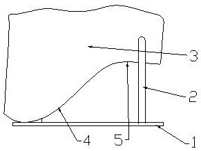
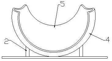
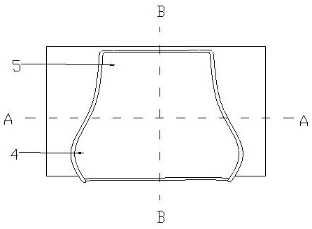
[0031] A head fixing device includes a base 1, a support rod 2 and a head support plate 3, and the inner surface of the head support plate 3 in contact with the skin is a smooth surface. In this embodiment, the head support plate 3 is an integrally formed neck support plate 5 and a brain support plate 4 . According to the design of the lying state of the specimen when dissecting the specimen, the bottom of the brain support plate 4 is fixedly connected to the base 1 ; the bottom of the neck support plate 5 is fixedly connected to the upper end of the support rod 2 , and the lower end of the support rod 2 is fixedly connected to the base 1 . According to the present invention, the support points from the neck to the head are arranged according to the arc of the human body. The bottom of the brain support plate 4 is the head pillow point, the brain support plate 4 extends from the pillow point to both sides of the head, and ends at the mid-vertical line; the neck support plate 5...

Embodiment 2

[0033] like Figure 4 As shown, the edges of the brain support 4 and / or the neck support 5 are configured as everted lip structures 6 . This embodiment avoids the compression of the specimen by the sharp edge that appears due to the sudden cut-off of the pallet surface. The second embodiment is suitable for the support plate, especially the upper edge structure design of the two sides of the brain support plate 4 for clamping the head. For the pallet that expands to the two upper ends of the pallet, the lip structure 6 does not need to be designed on the upper edge. Further, the inner side of the lip structure 6 is inlaid with a cushion 7 . The cushion 7 is arranged along the lip structure 6 . Cushion 7 further eliminates sharper, hard points of contact between the device and the head.

Embodiment 3

[0035] like Figure 5 As shown, the head support plate 3 is composed of an inner support layer 31 and an outer support layer 32 .

[0036] Implement three improvement structure one: refer to Image 6 As shown, the inner support layer 31 is a soft and elastic structural layer, the outer support layer 32 is a hard support layer, the bottom surface of the inner support layer 31 is evenly provided with support blocks 9, and the support block 9 and the inner support layer also need to be made of soft , with elastic material. The support block 9 may be a structure integrally injection-molded with the inner support layer 31 . Its material can be made of Q-bounce materials such as rubber or silicone, which can not only have a soft touch, but also have a smooth and waterproof surface. The inner support layer 31 and the support block 9 can be taken out from the outer support layer 32 for cleaning. After the inner support layer 31 is placed in the outer support layer 32 , the bottom ...


PUM


Abstract

The invention relates to a head fixing device which comprises a base, a supporting rod and a head supporting plate, and the head supporting plate comprises a neck supporting plate and a brain supporting plate; the bottom of the brain supporting plate is fixedly connected with the base; the bottom of the neck supporting plate is fixedly connected with the top end of the supporting rod; the bottom of the brain supporting plate is a head pillow point, and the brain supporting plate extends from the pillow point to the two sides of the head and stops to a middle vertical line; the neck supporting plate extends to the two sides of the neck from the bottom of the neck, the inner surface, in contact with the skin, of the head supporting plate is smooth, the supporting and fixing device with the smooth surface is adopted, the positions, in contact with the specimen, of the supporting and fixing device are in surface contact, and damage caused by the fixing structure to the specimen body is effectively avoided.

Description

technical field [0001] The invention belongs to the field of medical applied anatomy, in particular to a head fixing device. Background technique [0002] Applied anatomy is a relatively independent discipline developed on the basis of systematic anatomy and regional anatomy. Combining clinical operations and problems with anatomical human body structure to explain or find answers to questions, this field involves the brain, neck, limbs, chest and abdomen, pelvis, etc., laying a solid foundation for in-depth research in clinical medicine. [0003] Before performing facial dissection, the head of the corpse needs to be fixed first. Most of the devices used for fixing the head in the prior art are screw fixation. Specifically, the head is first placed on the operating table, and bolts are provided from both sides of the head to support it. , the top position on both sides of the head is clamped and fixed to prevent the head from tilting to both sides. This screw-fixed struct...

Claims


Application Information

Patent Timeline
Patent Type & Authority Applications(China)
IPC IPC(8): A61G13/12A61G13/00
CPCA61G13/121A61G13/128A61G13/0027
Inventor 徐颖李冬梅李力更周玉仓黄明高远高烨雪
Owner 唐山市第二医院
Why Eureka
Try Eureka