
Automatic reversing adjustment numerical control machining table for machining electromechanical shell castings

An automatic reversing and processing table technology, applied in metal processing equipment, metal processing machinery parts, manufacturing tools, etc., can solve problems such as consuming manpower and time, unable to adjust the direction of the workpiece, and affecting the processing quality of the workpiece, so as to improve the quality of the workpiece The effect of processing quality, avoiding multiple adjustments of direction and positioning work, saving manpower and time

Inactive Publication Date: 2022-06-24
太仓智升机械科技研发有限公司
View PDF0 Cites 0 Cited by
  • Summary
  • Abstract
  • Description
  • Claims
  • Application Information

AI Technical Summary

Problems solved by technology

[0002] As we all know, the electromechanical casing is the basic part of the generator, which is usually cast. After the electromechanical casing is cast, it needs to be fixed on the workbench in the machine tool, and the machining positions on the workpiece are processed by the machine tool. However, the existing workbench cannot adjust the direction of the workpiece, and the machine tool can only process the upper surface of the workpiece. When the other sides of the workpiece need to be processed, the workpiece needs to be removed and the direction of the workpiece must be adjusted, and then the workpiece must be fixed again on the On the fixed table, due to the large number of workpiece processing surfaces, it needs to adjust the direction multiple times, and the workpiece needs to be repositioned every time. At the same time, the workpiece has been adjusted and positioned many times, and its machining accuracy is reduced, which is likely to affect the processing quality of the workpiece

Method used


Image

  • Automatic reversing adjustment numerical control machining table for machining electromechanical shell castings
  • Automatic reversing adjustment numerical control machining table for machining electromechanical shell castings
  • Automatic reversing adjustment numerical control machining table for machining electromechanical shell castings

Examples


Embodiment Construction

[0029] The technical solutions in the embodiments of the present invention will be clearly and completely described below with reference to the accompanying drawings in the embodiments of the present invention. Obviously, the described embodiments are only a part of the embodiments of the present invention, rather than all the embodiments.

[0030] In the description of the present invention, it should be noted that "center", "upper", "lower", "left", "right", "vertical", "horizontal", "inner", "outer", etc. The indicated orientation or positional relationship is based on the orientation or positional relationship shown in the accompanying drawings, which is only for the convenience of describing the present invention and simplifying the description, rather than indicating or implying that the indicated device or element must have a specific orientation or a specific orientation. construction and operation, and therefore should not be construed as limiting the invention.

[00...


PUM


Abstract

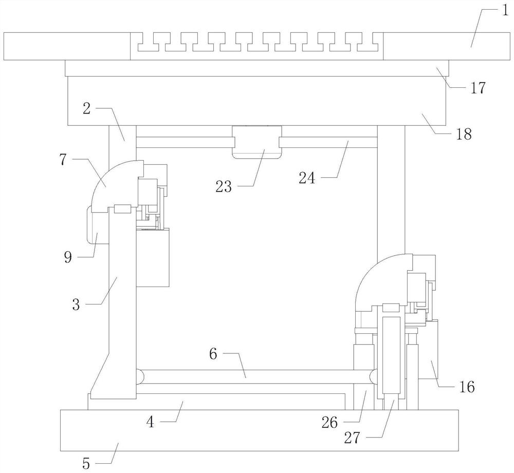
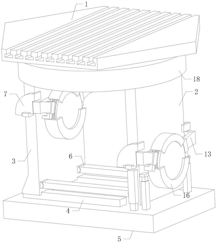
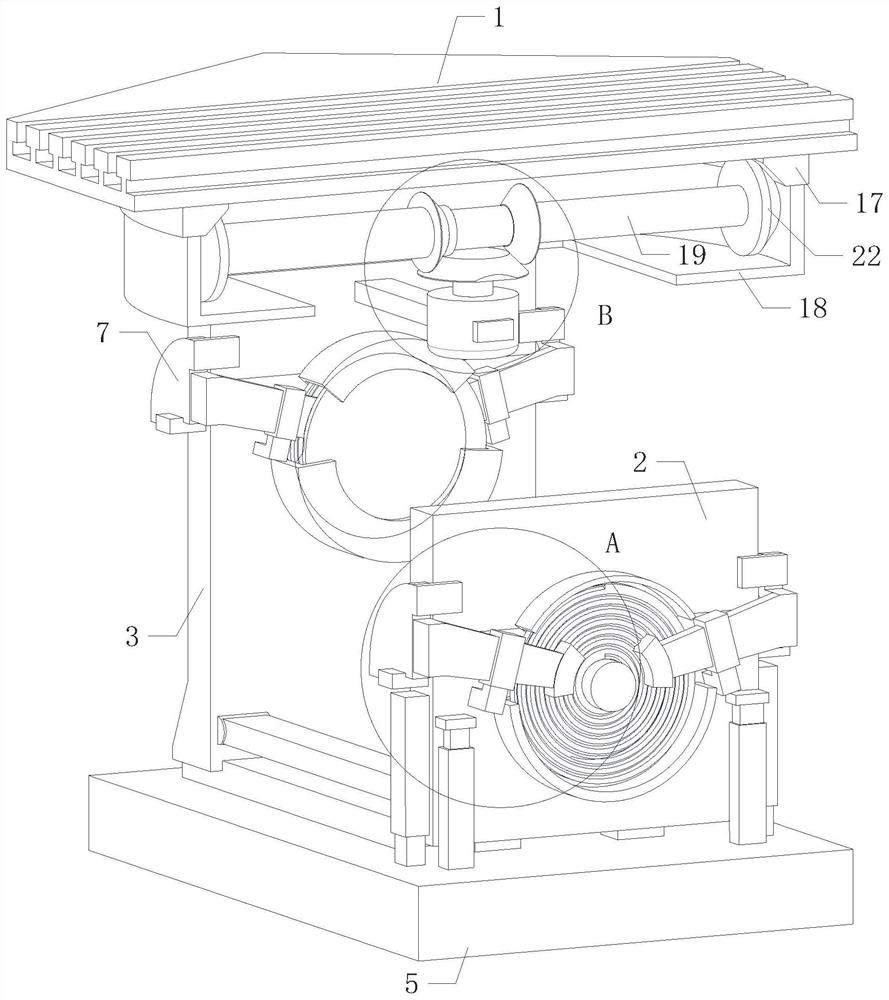
The invention relates to the technical field of mechanical tool equipment, in particular to an automatic reversing adjustment numerical control machining table for machining electromechanical shell castings, which comprises a working table, a fixing groove is formed in the working surface of the working table, a rotating mechanism is arranged on one side of the back surface of the working table, and the rotating mechanism is used for driving the working table to rotate; through automatic reversing adjustment of the direction of the workpiece, automatic conversion of all machining faces on the workpiece is facilitated, repeated direction adjustment and positioning work of the workpiece is avoided, the workpiece machining mode is simplified, manpower and time are saved, the working efficiency is improved, meanwhile, reduction of machining precision caused by repeated adjustment of the workpiece is avoided, and the workpiece machining quality is improved. The practicability is improved.

Description

technical field [0001] The invention relates to the technical field of mechanical tooling equipment, in particular to an automatic reversing adjustment numerical control machining table for machining electromechanical shell castings. Background technique [0002] As we all know, the electromechanical shell is the basic part of the generator, which is usually cast. After the electromechanical shell is cast, it needs to be fixed on the workbench in the machine tool, and the machining positions on the workpiece are processed by the machine tool. The existing worktable cannot adjust the direction of the workpiece, and the machine tool can only process the upper surface of the workpiece. When the other sides of the workpiece need to be processed, the workpiece needs to be removed and the direction of the workpiece needs to be adjusted, and then the workpiece is re-fixed on On the fixed table, due to the large number of workpiece processing surfaces, it needs to adjust the directi...

Claims


Application Information

Patent Timeline
Patent Type & Authority Applications(China)
IPC IPC(8): B23Q1/26B23Q3/06
CPCB23Q1/26B23Q3/06
Inventor 代会丽
Owner 太仓智升机械科技研发有限公司
Learn More