Isolation switch and static contact assembly thereof

A technology for isolating switches and static contacts, which is applied in air switch parts, switches with movable electrical contacts, contact heating/cooling, etc., can solve the problems of prone to discharge at the end of static contacts, and achieve guidance And the heat dissipation effect is good, the effect of ensuring safe use and avoiding tip discharge

Pending Publication Date: 2022-06-24
HENAN PINGGAO GENERAL ELECTRIC CO LTD +1
View PDF9 Cites 0 Cited by
  • Summary
  • Abstract
  • Description
  • Claims
  • Application Information

AI Technical Summary

Problems solved by technology

[0006] The purpose of the present invention is to provide a static contact assembly of a disconnector to solve the problem in the prior art that the end of the static contact is prone to discharge due to internal chamfering at the end of the static contact; the purpose of the present invention It is also to provide an isolating switch to solve the above-mentioned purpose

Method used


Image

  • Isolation switch and static contact assembly thereof
  • Isolation switch and static contact assembly thereof
  • Isolation switch and static contact assembly thereof

Examples


Embodiment 1

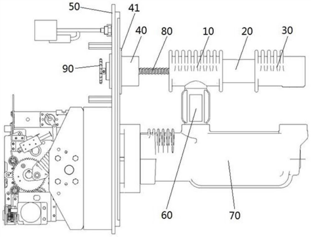
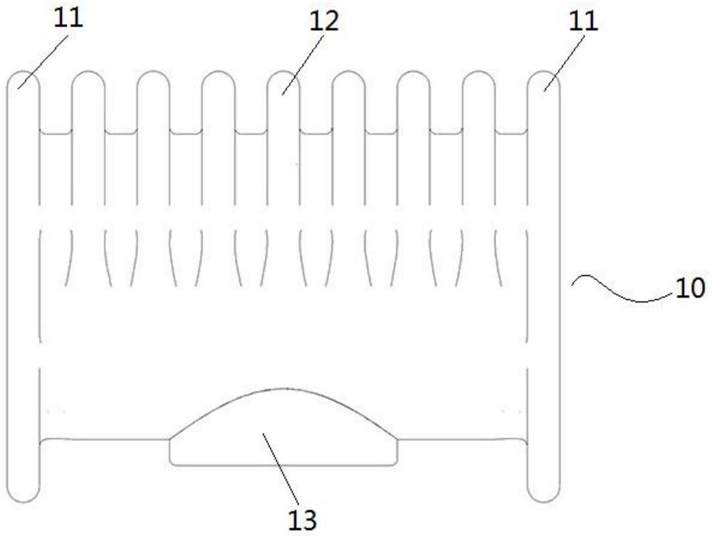
[0044] like figure 1 As shown, the isolating switch in this embodiment is a three-position isolating grounding switch, and the isolating switch includes a static contact and a moving contact 20 that is plugged into the static contact, wherein the static contact includes a middle static contact 10, and the middle static contact The contact 10 is provided with a first connection portion 13, and the first connection portion 13 is connected to the conductive seat 60 on the solid-sealed pole 70, wherein the solid-sealed pole 70 is fixed on the mounting plate 50 of the inflatable cabinet, and the first connection The portion 13 is connected to the conductive seat 60 , so that the intermediate static contact 10 is connected to the solid-sealed pole 70 through the connection of the first connection portion 13 to the conductive seat 60 .

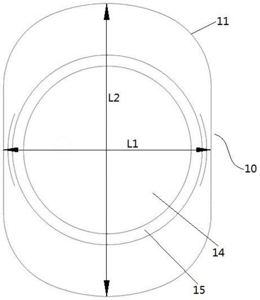
[0045] like image 3 As shown, the middle part of the intermediate static contact 10 is provided with a first axial through hole 14 extending along...

Embodiment 2

[0054] The difference between this embodiment and Embodiment 1 is that in Embodiment 1, the movable contact through hole 21 includes an internal thread segment 22 for threading with the insulating lead screw 80 and a heat dissipation segment provided with a heat dissipation groove. However, in this embodiment, the movable contact through hole 21 only includes the internal thread segment 22 for threaded engagement with the insulating lead screw 80 . At this time, only a part of the movable contact through hole 21 may be the thread segment 22 , or all of the thread segment may be included. twenty two.

Embodiment 3

[0056]The difference between this embodiment and Embodiment 1 is that in Embodiment 1, the movable contact 20 is provided with a movable contact through hole 21 extending along its own axial direction, and the movable contact through hole 21 includes a contact hole 21 for connecting with the insulating lead screw 80 . The inner thread segment 22 , that is, the movable contact 20 , is driven to move by the insulating lead screw 80 . In the present embodiment, the movable contact 20 may not be provided with the movable contact through hole 21. In this case, a rack is provided outside the movable contact 20, and is equipped with a gear that cooperates with the rack to drive the movable contact through the rack and pinion structure. 20 reciprocating movements.


PUM


Abstract

The invention relates to an isolating switch and a static contact assembly of the isolating switch, the static contact assembly comprises a static contact, the static contact is provided with an axial through hole for a moving contact to penetrate, the peripheral surface of the static contact is provided with heat dissipation fins, the heat dissipation fins comprise end heat dissipation fins located at the axial end of the static contact, the end heat dissipation fins are integrally formed on the static contact, and the end heat dissipation fins are arranged in the axial through hole. And the end part radiating fins are flush with the end surface of the corresponding end of the static contact, so that a plate electrode structure is formed at the end part of the corresponding end of the static contact. The problem that in the prior art, due to the fact that an inner chamfer is machined at the end of the static contact, the end of the static contact is prone to discharging can be solved.

Description

technical field [0001] The invention relates to an isolation switch and a static contact assembly of the isolation switch, in particular to a heat dissipation fin of the static contact. Background technique [0002] The domestic market of 12kV environmentally friendly inflatable cabinets is very large and the prospect is very broad. The environmental protection inflatable cabinets are usually equipped with three-position isolation and grounding switches. The three-position isolating grounding switch includes a grounding static contact, a middle static contact and an isolating static contact which are arranged at intervals along a straight line. When the moving contact is in contact with the grounding static contact, the three-position isolating grounding switch is in the grounding position. When the moving contact is in contact with the isolating static contact, the three-position isolating grounding switch is in the conducting position. When the moving contact is only in c...

Claims


Application Information

Patent Timeline
Patent Type & Authority Applications(China)
IPC IPC(8): H01H1/62H01H31/02H01H31/26
CPCH01H1/62H01H31/02H01H31/26
Inventor 侯宾宾李小叶赵辉高胜豪田红超刘永豪高正付秦悦悦高钰张俊范建阎志朋郭媛媛张恒朱苛娄李军浩鲁世浩
Owner HENAN PINGGAO GENERAL ELECTRIC CO LTD
Why Eureka
Try Eureka