Large-current contact element and flat connector

A contact and high-current technology, applied in the direction of contact parts, connections, electrical components, etc., can solve the problems of low space utilization rate of electrical contact area, increased use of materials, and large occupied area, so as to achieve small space applications and improve electrical conductivity The effect of simple cross-section and manufacturing process

Pending Publication Date: 2022-06-24
SHENZHEN NETSOK TECH CO LTD
View PDF0 Cites 0 Cited by
  • Summary
  • Abstract
  • Description
  • Claims
  • Application Information

AI Technical Summary

Problems solved by technology

However, as we all know, a circle with the same perimeter occupies the largest area, resulting in a simultaneous increase in the volume and mass of the connector, which in turn makes the installation space in the car tight, restricts the size design of the battery and other systems, and also violates the principles of lightweight design. Thus affecting the cruising range of the vehicle
Moreover, the traditional circular connector socket is limited by the minimum thickness of the punch in the characteristics of the stamping process, and there will be a bottleneck in the number of contacts of the socket reed contact, so that in the same space, the space utilization of the electrical contact area is extremely high. Low
The increase in the materials used in the product and the complexity of the process also greatly intensified the pressure on the user's use cost

Method used


Image

  • Large-current contact element and flat connector
  • Large-current contact element and flat connector
  • Large-current contact element and flat connector

Examples


Embodiment 1

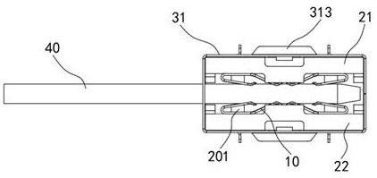
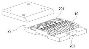
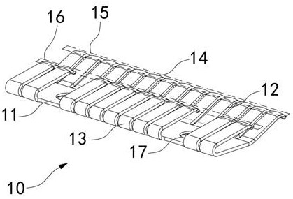
[0039] Please refer to Figure 1-4 , a large current contact piece 10 , comprising a rectangular sheet body 11 .

[0040] One side of the rectangular sheet body 11 is provided with a plurality of upturned elastic sheets 12, and the other side of the rectangular sheet body 11 is provided with a plurality of bending elastic sheets 13, and the upturning direction of the upturned elastic sheet 12 is the same as the bending direction of the bending elastic sheet 13. The plane defined by the end of the raised elastic piece 12 and the end of the bent elastic piece 13 is parallel to the rectangular sheet body 11 .

[0041] The ends of the plurality of upturned elastic sheets 12 form the first contact area 15, and the ends of the plurality of bent elastic sheets 13 form the second contact area 16. When the contact piece 10 is in contact with the external insert 40, the first contact area 15 and The second contact area 16 is in common contact with the external inserts 40, which increas...

Embodiment 2

[0061] Please refer to Figure 18 , this embodiment replaces the first plywood 21 and the second plywood 22 with a pair of third plywood 23 on the basis of the first embodiment, and the third plywood 23 is stepped (the height of the second plywood 22 is twice as high as that of the third plywood 23 height), a pair of third splints 23 are arranged opposite to each other, the same side of the pair of third splints 23 is fixedly connected, and the other side of the pair of third splints 23 is spaced with gaps, and multiple sets of positioning units are placed in a pair of On the opposite end surface of the other side of the third clamping plate 23 , the positioning columns 201 of each group of positioning units are clipped into the fixing holes 17 for fixing (please refer to the first embodiment). The other sides of the pair of third splints 23 are provided with card holes 203 , and both the first card 311 in the first transformation pattern and the fourth card 322 in the second ...

Embodiment 3

[0063] Please refer to Figure 19 and Figure 20 , this embodiment replaces the first plywood 21 and the second plywood 22 with the fourth plywood 24 and the fifth plywood 25 on the basis of the first embodiment, the fourth plywood 24 is a straight plate structure, and the two side walls of one end of the fourth plywood 24 There is a pressing piece 241, the fourth plywood 24 and two pieces of wire pressing piece 241 form a U-shaped structure, the fifth plywood 25 is stepped, and one end of the fifth plywood 25 is provided with a fixing bar 251, and the fixing bar 251 is inserted into the U-shaped structure It is fixedly connected with one end of the fourth plywood 24, the other end of the fourth plywood 24 and the other end of the fifth plywood 25 are spaced with a gap, and multiple sets of positioning units are respectively placed on the other end of the fourth plywood 24 and the other end of the fifth plywood 25 opposite. On the end surface of the locating unit, the locatin...


PUM


Abstract

The invention discloses a high-current contact and a flat connector, the contact comprises a rectangular sheet body, one side of the rectangular sheet body is provided with a plurality of warped elastic sheets, the other side of the rectangular sheet body is provided with a plurality of bent elastic sheets, the warped direction of the warped elastic sheets is the same as the bending direction of the bent elastic sheets, and the warped elastic sheets and the bent elastic sheets are arranged on the rectangular sheet body. And a plane determined by the end part of the warped elastic sheet and the end part of the bent elastic sheet is parallel to the rectangular sheet body. According to the large-current contact piece and the flat connector, the end portions of the multiple warping elastic pieces form the first contact area, the end portions of the multiple bending elastic pieces form the second contact area, when the contact piece makes contact with an external insertion piece, the first contact area and the second contact area make contact with the external insertion piece together, the conductive cross section is improved, the electric loss is greatly reduced, and the service life of the contact piece is prolonged. Therefore, larger current can be borne; the structure is in a sheet shape, occupies a small space relative to a cylinder, can realize small-space application, and is simpler and more economical in manufacturing process relative to a cylinder structure, so that the production cost is reduced.

Description

technical field [0001] The invention relates to the technical field of new energy accessories and connectors, in particular to a high-current contact piece and a flat connector. Background technique [0002] With the development of the electric vehicle industry, the market has put forward higher requirements for the cruising range of electric vehicles; however, the market has also put forward higher requirements for cost reduction in order to facilitate the promotion of new energy vehicles. The connector is an important part of the electric vehicle, and it also needs to simultaneously meet the requirements of higher carrying current, miniaturization, and low cost. [0003] At present, the connectors used in new energy vehicles generally use circular sockets, that is, the pin sockets are all circular, and most of the parts are made by machining and stamping process. However, as we all know, the circle occupies the largest area under the same perimeter, which leads to the sim...

Claims


Application Information

Patent Timeline
Patent Type & Authority Applications(China)
IPC IPC(8): H01R13/02H01R13/24
CPCH01R13/02H01R13/2414H01R13/2457
Inventor 倪泉许公杰
Owner SHENZHEN NETSOK TECH CO LTD
Why Eureka
Try Eureka