Positioning device for acupuncture and moxibustion
A positioning device and acupuncture technology, applied in the medical field, can solve the problems of cumbersome operation, bacterial infection, acupuncture point displacement, etc., and achieve the effects of flexible operation, saving work pressure, and high accuracy of acupuncture and moxibustion
- Summary
- Abstract
- Description
- Claims
- Application Information
AI Technical Summary
Problems solved by technology
Method used
Image
Examples
Embodiment 1
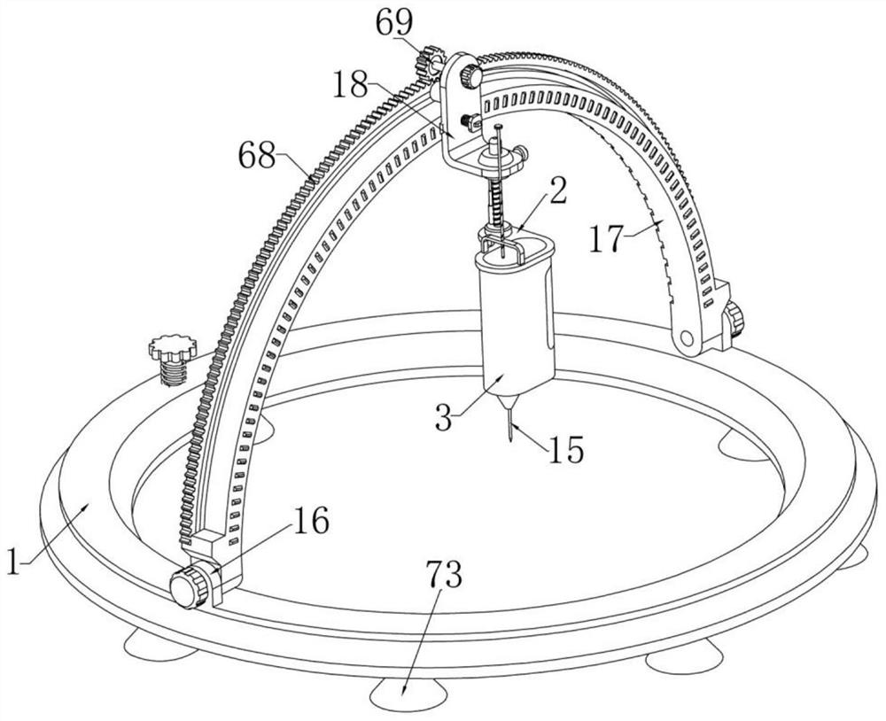
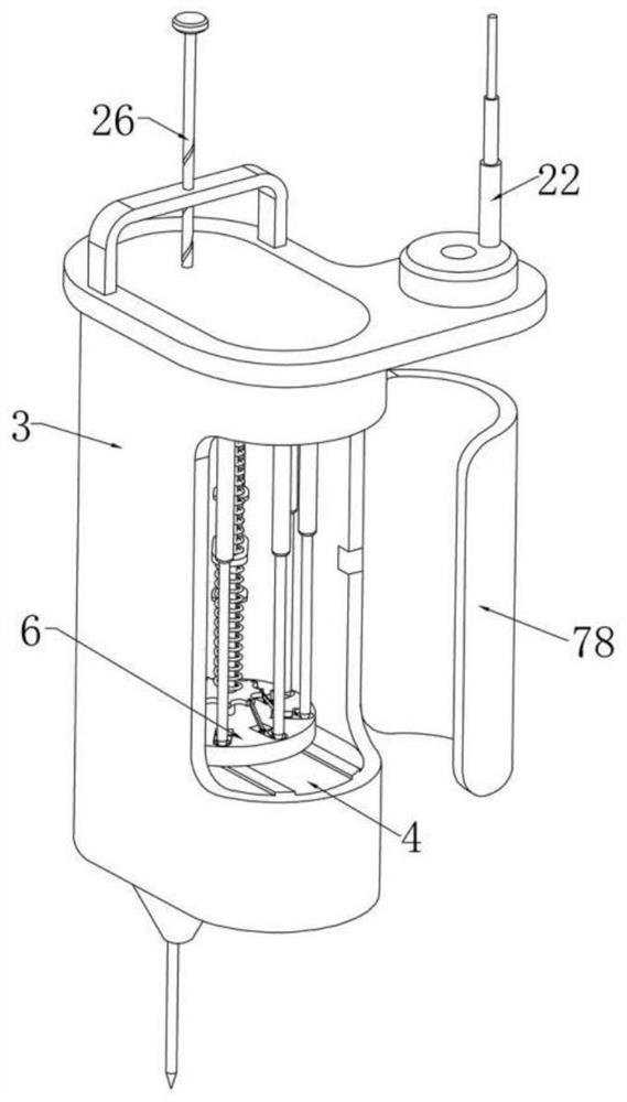
[0045] Example one, as Figure 1-19 As shown, a positioning device for acupuncture includes a positioning ring 1, an adjustment device is rotatably installed on the upper end of the positioning ring 1, the adjustment device can swing back and forth on the positioning ring 1, and the adjustment device is installed on the positioning ring 1. There are special-shaped plates 2 that move up and down, such as image 3 As shown in the figure, the lower end of the special-shaped plate 2 is fixedly installed with an acupuncture cylinder 3, and the upper and lower ends of the acupuncture cylinder 3 are respectively fixed with a limit plate 4, and there is a certain distance between the upper limit plate 4 and the special-shaped plate 2 , a support rod 5 is slidably installed left and right between the two limit plates 4, and two ends of the support rod 5 are respectively fixed with clamping disks 6, and each of the clamping disks 6 is respectively limited on the same side. Sliding left...
Embodiment 2
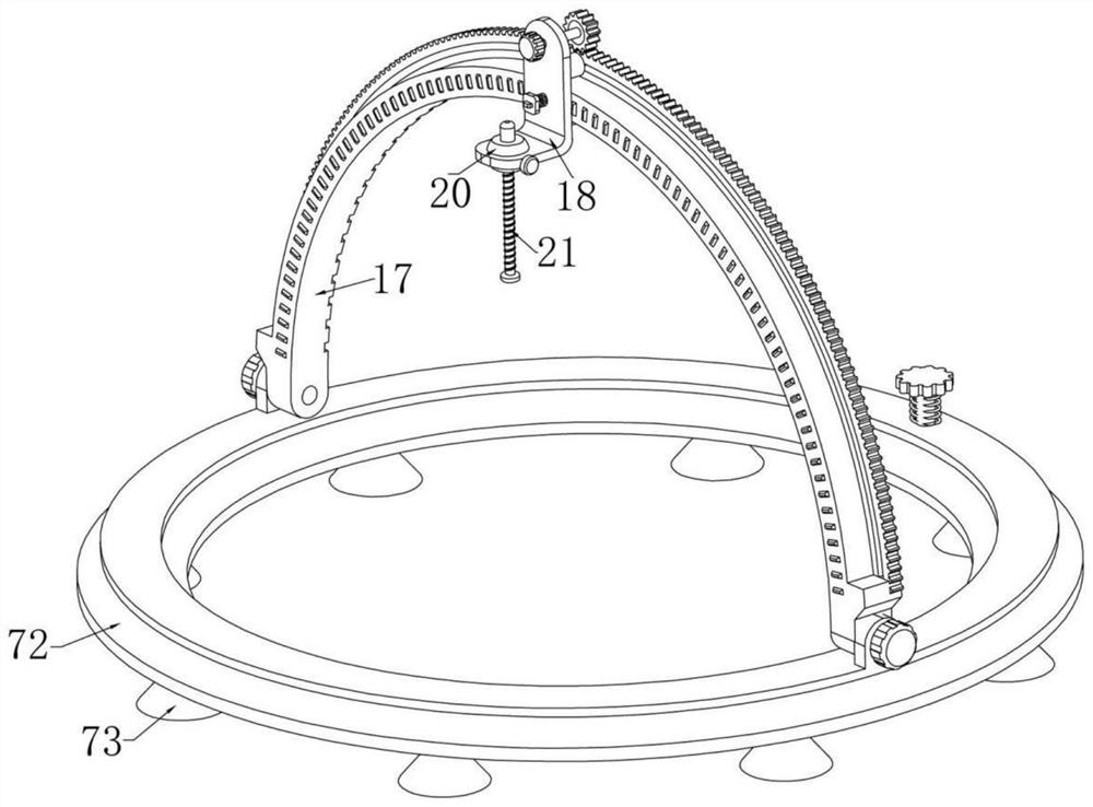
[0049] Embodiment 2, on the basis of Embodiment 1, as Figure 1-3 As shown, the upper end of the positioning ring 1 is fixedly installed with two left-right symmetrical positioning blocks 16, and each of the positioning blocks 16 is respectively screwed with a bolt installed on one end of the arc strip 17, and the adjustment The assembly includes an arc-shaped strip 17 rotatably installed between the two positioning blocks 16, and an L-shaped plate 18 is slidably installed on the right end surface of the arc-shaped strip 17, such as Figure 4 As shown, the left end of the L-shaped plate 18 is fixedly installed with a cylinder 19 that is slidably installed on the upper end of the arc-shaped bar 17. The cylinder 19 can slide along the upper end surface of the arc-shaped bar 17. The L-shaped plate 18 The right end of the ball is connected with an adjusting ball 20, and an adjusting screw 21 is rotatably mounted on the adjusting ball 20 and is threadedly mounted on the special-sha...
Embodiment 3
[0051] Embodiment 3, on the basis of Embodiment 1, as Figure 6-8 As shown, the two limit plates 4 are provided with introduction holes. When the clamping plate 6 is rotated, each insertion hole 8 on the clamping plate 6 corresponds to the introduction hole. The upper end of the limit plate 4 is rotatably installed with a lower pulley 24 corresponding to the introduction hole, a boss 25 is fixedly installed inside the lower pulley 24, and a driving rod 26 is slidably installed in the lower pulley 24, so The diameter of the inner hole of the lower pulley 24 is larger than the diameter of the driving rod 26 . The driving rod 26 is provided with a threaded groove 27 that cooperates with the boss 25 . Self-locking, the driving rod 26 can only move up and down without rotating. When the driving rod 26 slides down, the boss 25 will rotate along the threaded groove 27, and the driving rod 26 can pass through the threaded groove. 27 drives the lower pulley 24 to rotate;
[0052] lik...
PUM
 Abstract
Description
Claims
Application Information
 - R&D
- Intellectual Property
- Life Sciences
- Materials
- Tech Scout
- Unparalleled Data Quality
- Higher Quality Content
- 60% Fewer Hallucinations
Browse by: Latest US Patents, China's latest patents, Technical Efficacy Thesaurus, Application Domain, Technology Topic, Popular Technical Reports.
© 2025 PatSnap. All rights reserved.Legal|Privacy policy|Modern Slavery Act Transparency Statement|Sitemap|About US| Contact US: help@patsnap.com


