Temperature control clamping device, crimping box and error code testing device

A technology of clamping device and temperature control module, which is applied in the field of digital communication, can solve the problems of module scratches, etc., and achieve the effects of not easy to scratch, effective crimping, and guaranteed crimping

Active Publication Date: 2022-06-28
STELIGHT INSTR CO LTD
View PDF10 Cites 0 Cited by
  • Summary
  • Abstract
  • Description
  • Claims
  • Application Information

AI Technical Summary

Problems solved by technology

Because the optical module needs to be in good contact with the heat sink, it is easy to scratch the module during the insertion and removal process

Method used


Image

  • Temperature control clamping device, crimping box and error code testing device
  • Temperature control clamping device, crimping box and error code testing device
  • Temperature control clamping device, crimping box and error code testing device

Examples


Embodiment Construction

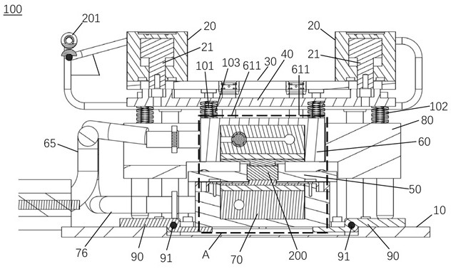
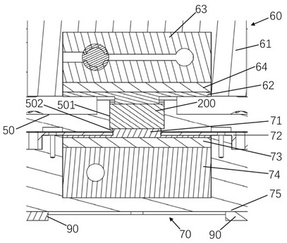
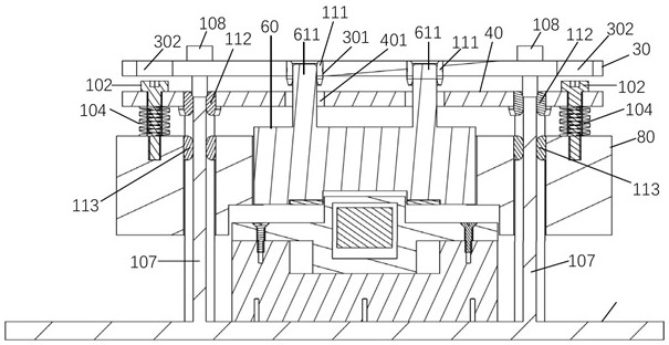
[0057] figure 1 A cross-sectional view of a temperature-controlled clamping device 100 (in a crimped state) according to one embodiment of the present invention. figure 2 Yes figure 1 Partial enlarged view at A. image 3 It is a structural cross-sectional view of the temperature-controlled clamping device 100 at the second fastener 102 according to an embodiment of the present invention. The present invention also provides a temperature-controlled clamping device 100 for crimping and temperature control of the optical module 200. In one embodiment, such as figure 1 As shown, the temperature control clamping device 100 includes a fixed base plate 10, a cylinder 20, a cylinder support plate 30, a movable push plate 40, a limit plate 50, an upper temperature control module 60, a lower temperature control module 70, a pressing block structure 80 and Lever plate 90. The cylinder 20 has a retractable plunger rod 21 . The cylinder support plate 30 is fixedly connected with the ...


PUM


Abstract

The invention provides a temperature control clamping device, a crimping box and an error code testing device, and belongs to the technical field of digital communication. The temperature control clamping device comprises a fixed substrate; the air cylinder is provided with a telescopic plunger rod; the air cylinder supporting plate is fixedly connected with the fixed base plate and used for fixing the air cylinder; the movable push plate is located below the air cylinder supporting plate and fixedly connected with the plunger rod. The limiting plate is fixedly connected with the fixed substrate and is used for penetrating through the optical module; the upper temperature control module is positioned above the optical module and is hung at the movable push plate through a first fastener; the lower temperature control module is positioned below the optical module; the pressing block structure is hung at the movable push plate through a second fastener; the lever plate is rotationally connected with the fixed base plate through a rotating shaft, the axis of the rotating shaft is horizontally arranged, and the upper surfaces of the two ends of the lever plate are opposite to the bottom of the pressing block structure and the bottom face of the lower temperature control module respectively. According to the temperature control clamping device, the crimping box and the error code testing device, the surface quality of the optical module can be ensured.

Description

technical field [0001] The invention relates to the technical field of digital communication, in particular to a temperature control clamping device, a crimping box and a code error testing device. Background technique [0002] In the current optical module test, the current conventional practice is to use screws or elbow clips to fasten the module to the temperature control module (semiconductor cooling chip + heat sink + water cooling head). Because the optical module needs to be in good contact with the heat sink, the module is prone to scratches during the process of plugging and unplugging. Some optical module manufacturers will use a kind of thin and wear-resistant medium such as high temperature tape to be placed between the optical module and the heat sink, which will improve the appearance of the optical module by losing the test efficiency. SUMMARY OF THE INVENTION [0003] An object of the first aspect of the present invention is to provide a temperature-contro...

Claims


Application Information

Patent Timeline
Patent Type & Authority Applications(China)
IPC IPC(8): B25B27/02B25B11/00G01M11/00
CPCB25B11/00G01R1/06711G01R1/06722G01R31/2891G01R35/00G01J5/00
Inventor 邓仁辉周晓峰廉哲
Owner STELIGHT INSTR CO LTD
Why Eureka
Try Eureka