Building wall punching device and using method thereof

A drilling device and a technology for building walls, which are used in work accessories, manufacturing tools, stone processing tools, etc., can solve the problems that the drill bit cannot punch rectangular holes and the operation is cumbersome, so as to facilitate replacement, improve stability, and facilitate The effect of disassembly

Pending Publication Date: 2022-06-28
杨兰英
View PDF1 Cites 0 Cited by
  • Summary
  • Abstract
  • Description
  • Claims
  • Application Information

AI Technical Summary

Problems solved by technology

[0006] The invention provides a building wall punching device and its use method, which has the beneficial effects of being convenient to directly drill rectangular holes, stable structure, and convenient operation, and solves the problem that the traditional drill bit mentioned in the background technology above cannot drill rectangular holes. hole, the operation is more cumbersome

Method used


Image

  • Building wall punching device and using method thereof
  • Building wall punching device and using method thereof
  • Building wall punching device and using method thereof

Examples


Embodiment 1

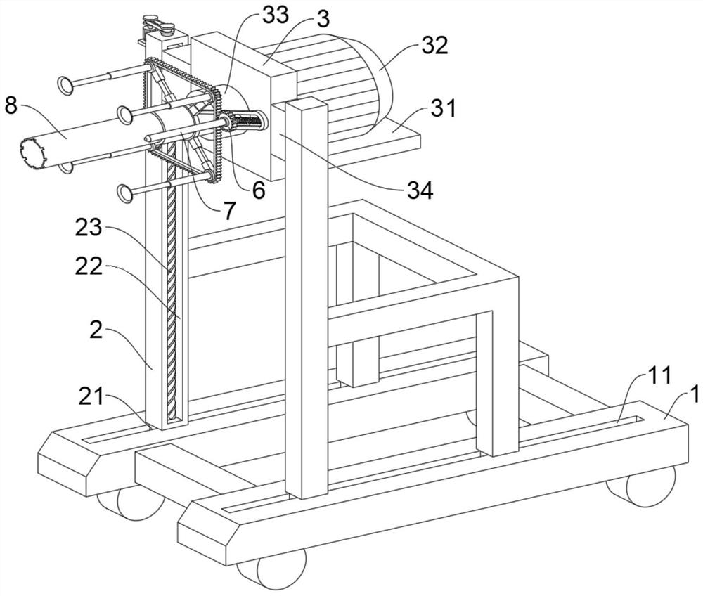
[0035] This embodiment is intended to facilitate solving the problem of how to ensure that the device can drill a rectangular hole at one time, please refer to Figure 1-2, a construction wall punching device, comprising a support frame 3, one end of the support frame 3 is fixedly installed with a support plate 31, a servo motor 32 is fixedly installed on the support plate 31, and the output end of the servo motor 32 is connected to the support frame 3 through interpenetration , and is connected with a connecting shaft 33, one end of the connecting shaft 33 is installed with a first drill bit 8, both ends of the outer wall of the support frame 3 are fixedly installed with a first slider 34, and both ends of the support frame 3 are also installed with vertical rods 2, vertical The inner side wall of the rod 2 is provided with a first chute 22, the first chute 22 is connected with a screw rod 23, the screw rod 23 is threadedly connected with the first slider 34, and the lower end...

Embodiment 2

[0044] This embodiment is intended to facilitate solving the problem of how to stabilize the gear 6 and the second drill bit 7. This embodiment is an improvement made on the basis of Embodiment 1. For details, please refer to figure 1 , figure 2 and Figure 5 The sliding block 53 is sleeved with a collar piece 52 , a spring 51 is fixedly installed on the outer wall of the collar piece 52 , and one end of the spring 51 away from the collar piece 52 is fixedly connected to the inner wall of the sliding rod 5 .

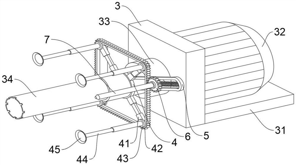
[0045] The diameters of each edge of the chain rack 42 from the connecting shaft 33 are different. The gear 6 rotates along the chain rack 42 and slides on the sliding rod 5. During the sliding process, the spring 51 can expand and contract. Under the action of the spring 51 , which can ensure that the gear 6 can always adhere to the side wall of the chain-shaped rack 42 for rotation and autorotation, so as to improve the stability of the second drill bit 7 .

[0046]...

Embodiment 3

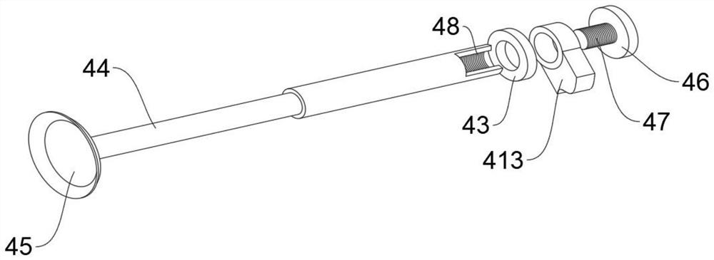
[0050] This embodiment is intended to facilitate solving the problem of how to drill rectangular holes of different sizes. This embodiment is an improvement made on the basis of Embodiment 2. For details, please refer to Figure 1-4 The support rod 41 is also provided with a cavity 411, an electric lifting rod 412 is installed in the cavity 411, an inner rod 413 is fixedly installed at one end of the electric lifting rod 412, and one end of the inner rod 413 is slidably connected with the chain rack 42.

[0051] Open the electric lift rod 412 to make it extend, the distance between the inner rods 413 can be increased, and it is convenient to install the chain rack 42 with a larger diameter, so the rectangle drilled by the second drill bit 7 can be enlarged.

[0052] An end of the inner rod 413 away from the electric lift rod 412 is inserted with a squeeze rod 44 , one end of the squeeze rod 44 is fixedly installed with a suction cup 45 , and the upper middle of the squeeze rod ...


PUM


Abstract

The invention relates to the technical field of wall surface punching, and discloses a building wall body punching device and a using method thereof.The building wall body punching device comprises a supporting frame, a supporting plate is fixedly installed at one end of the supporting frame, a servo motor is fixedly installed on the supporting plate, and the output end of the servo motor is connected with the supporting frame in a penetrating and inserting mode; a connecting shaft is connected to the supporting frame, a first drill bit is installed at one end of the connecting shaft, first sliding blocks are fixedly installed at the two ends of the outer wall of the supporting frame, vertical rods are further installed at the two ends of the supporting frame, first sliding grooves are formed in the inner side walls of the vertical rods, spiral lead screws are connected to the first sliding grooves, and the spiral lead screws are in threaded connection with the first sliding blocks; in the drilling process, firstly, a small round hole is drilled by the first drill bit, the bearing capacity of the drilled wall is reduced, and then a rectangular hole is drilled by the second drill bit, so that the burden of the second drill bit is reduced, and the rectangular hole is formed more easily.

Description

technical field [0001] The invention relates to the technical field of wall punching, in particular to a building wall punching device and a method for using the same. Background technique [0002] Drilling device refers to the general term for equipment used to process holes in solid materials. Common drilling devices include electric drills, drilling machines, etc. With the further development of the processing technology, the efficiency of the drilling device has also been greatly improved. After the construction of the building foundation is completed, in order to facilitate the further layout of the pipeline and the installation of the air conditioner in the later stage, it is necessary to drill holes in the designated positions of the concrete wall. [0003] Chinese invention patent CN202011290603.1 discloses a wood board punching device for civil engineering. It includes: a base plate 1, a support base 2 is installed at the bottom of the base plate 1, a chassis 3 is...

Claims


Application Information

Patent Timeline
Patent Type & Authority Applications(China)
IPC IPC(8): B28D1/14B28D7/00
CPCB28D1/146B28D7/00
Inventor 杨兰英
Owner 杨兰英
Why Eureka
Try Eureka