Knitwear dyeing and drying integrated device

An integrated technology for knitwear, applied in the field of knitwear dyeing and drying integrated devices, can solve the problems of inability to achieve rapid cooling of knitwear, low processing efficiency, effective heat utilization, etc., and achieve full dyeing and rapid cooling operations and energy utilization. The effect of high conversion rate and low processing energy consumption

Pending Publication Date: 2022-06-28
NANTONG DONGDI TEXTILE
View PDF4 Cites 0 Cited by
  • Summary
  • Abstract
  • Description
  • Claims
  • Application Information

AI Technical Summary

Problems solved by technology

[0005] 1. The existing devices usually use a dyeing device and a drying device to dye and dry the knitwear respectively. At this time, the processing method is inefficient and needs to transfer the knitwear continuously, which is troublesome;
[0006] 2. The existing device usually fixes the roll-shaped knitwear before dyeing. This dyeing method cannot make the inside of the roll-shaped knitwear fully contact with the dyeing solution, and the problem of uneven dyeing will occur;
[0007] 3. Knitwear needs to be dried after dyeing, but the existing device cannot effectively use the heat during drying, and cannot realize rapid cooling of knitwear, which has certain limitations;

Method used


Image

  • Knitwear dyeing and drying integrated device
  • Knitwear dyeing and drying integrated device
  • Knitwear dyeing and drying integrated device

Examples


Embodiment Construction

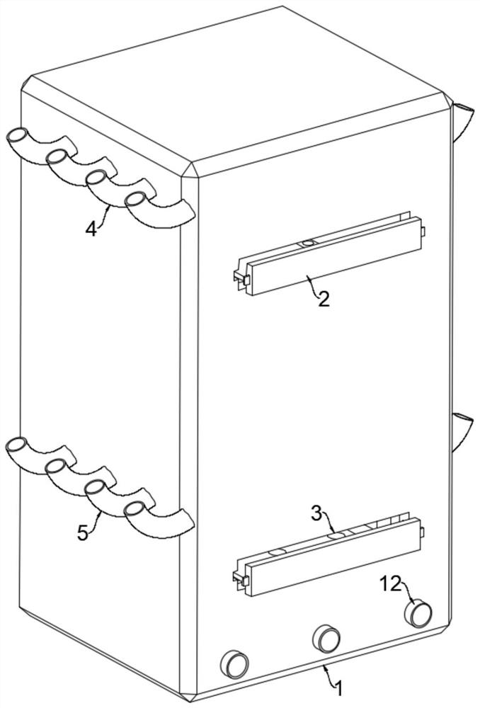
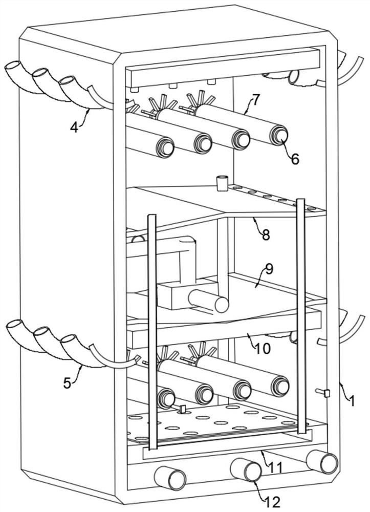
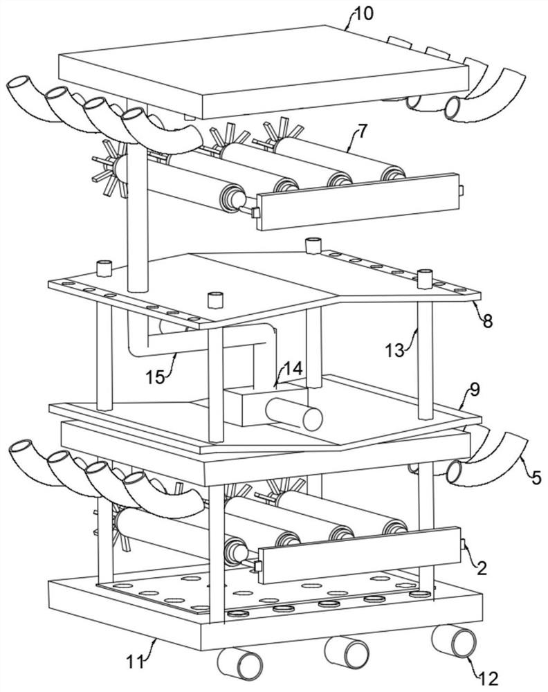
[0034] refer to Figure 1-2 , an integrated device for dyeing and drying knitted fabrics, comprising a box body 1, in which a swash plate 1 8, a swash plate 2 9, a gas collecting box 11 and two liquid storage boxes 10 are fixedly installed;

[0035] It is worth noting that: the upper area of ​​the box body 1 located on the slant plate 1 8 is the placement and processing area of ​​the first batch of knitwear (hereinafter referred to as the processing area 1), and the box body 1 is located on the slant plate 2 9 and the gas collecting box. The area between 11 is the placement and processing area of ​​the second batch of knitted fabrics (hereinafter referred to as the processing area 2), and the area in the box 1 between the sloping plate 1 8 and the sloping plate 2 9 is the storage area for dyeing liquid (hereinafter referred to as the second swash plate). referred to as the storage area).

[0036] refer to Figure 1-3 , two placement mechanisms are installed in the box body 1...


PUM


Abstract

The invention discloses a knitwear dyeing and drying integrated device which comprises a box body, two placing mechanisms are installed in the box body, a plurality of heating rollers are rotatably installed in the box body through a plurality of rotating rollers, a driving wheel is fixedly installed on each rotating roller, and a first inclined plate, a second inclined plate, a gas collection box and two liquid storage boxes are fixedly installed in the box body. A liquid guide mechanism is installed between the second inclined plate and the two liquid storage boxes, a plurality of impact pipes are fixedly installed on the two liquid storage boxes, each impact pipe is located above the corresponding driving wheel, a gas guide mechanism is installed on the gas collecting box, and a plurality of semi-permeable liquid discharging pipes are fixedly installed on the gas collecting box. The knitwear dyeing and drying device has the advantages that the knitwear dyeing and drying operation can be synchronously carried out, mutual utilization and conversion of energy are fully carried out by utilizing the principles of gravitational potential energy, cold and hot gas replacement and the like, full dyeing and rapid cooling operation of the knitwear can be realized, the processing energy consumption is low, and the efficiency is high.

Description

technical field [0001] The invention relates to the technical field of knitwear, in particular to an integrated device for dyeing and drying knitwear. Background technique [0002] Knitwear refers to items knitted with sewing needles. In order to increase its beauty and diversity after knitting, roll-shaped knitwear is usually dyed and dried by dyeing and drying devices after processing. operate; [0003] After searching, the Chinese invention patent with the patent number of CN112577299A discloses a drying device for bleaching and dyeing knitwear, which includes a drying room, a bracket arranged on the ground to support the drying room, and a depression directly below the drying room. To the lift chamber below the ground, the knitwear transport assembly located in the lift chamber and extending into the drying chamber. A heating air supply component and a far-infrared heating tube are arranged at the upper and lower intervals inside the drying chamber. The knitwear transm...

Claims


Application Information

Patent Timeline
Patent Type & Authority Applications(China)
IPC IPC(8): D06B1/08D06B23/04D06B23/20D06B23/22F26B21/00
CPCD06B1/08D06B23/04D06B23/20D06B23/22F26B21/001
Inventor 卢红卫
Owner NANTONG DONGDI TEXTILE
Why Eureka
Try Eureka