

Bridge construction supporting method
A support method and bridge construction technology, applied in bridges, bridge construction, erection/assembly of bridges, etc., can solve problems such as inability to protect, avoid falling objects from high altitudes, improve overall protection performance, and reduce injuries caused by falling objects Effect
- Summary
- Abstract
- Description
- Claims
- Application Information
AI Technical Summary
Problems solved by technology
Method used
Image

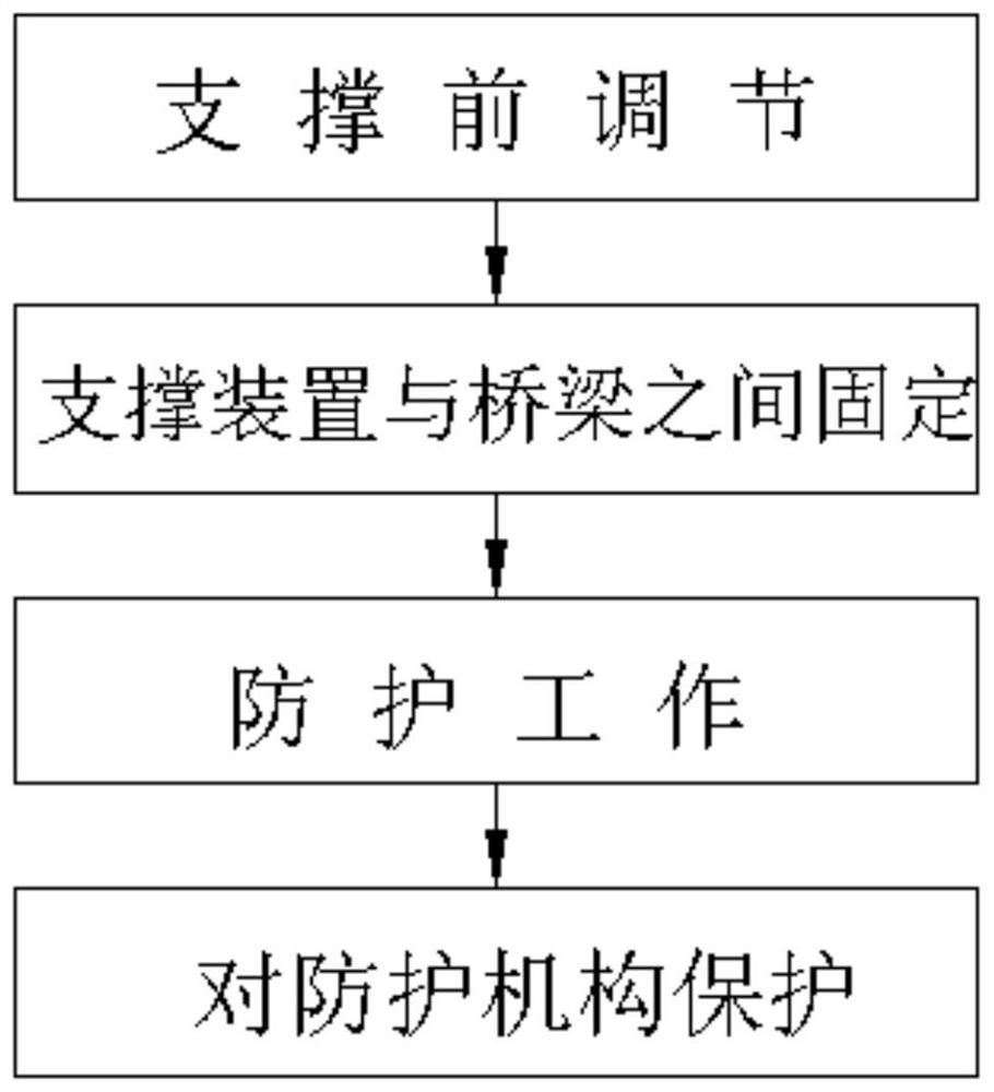
Examples
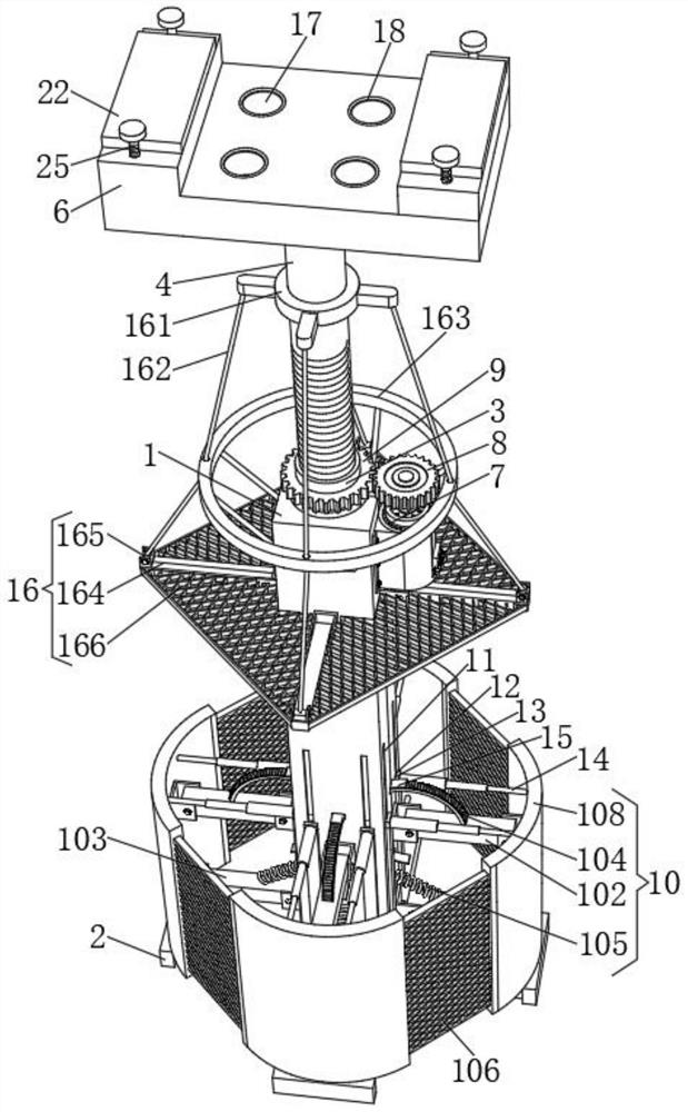
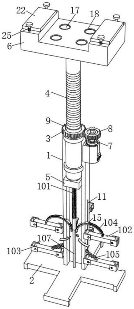
Embodiment 1
[0034] see Figure 2-8 , the supporting device includes a supporting square column 1 , and a cross base 2 is fixed at the bottom end of the supporting square column 1 . The top of the inner cavity of the supporting square column 1 is rotatably connected with a threaded sleeve 3 through a bearing, and the threaded sleeve 3 is threadedly connected with a lead screw 4 . The bottom end of the screw rod 4 is fixed with a moving block 5 , and the moving block 5 is slidably arranged in the supporting square column 1 . The top of one side of the supporting square column 1 is fixed with a motor 7 through a mounting seat, the output end of the motor 7 is fixed with a first cylindrical gear 8, one side of the first cylindrical gear 8 is meshed with a second cylindrical gear 9, and the second cylindrical gear 9 The inner ring is sleeved on the threaded sleeve 3. The top of the screw rod 4 is fixed with a support base 6, and the motor 7 is used to provide a driving source, so that the sc...
Embodiment 2
[0037] see Figure 2-8 , the supporting device includes a supporting square column 1 , and a cross base 2 is fixed at the bottom end of the supporting square column 1 . The top of the inner cavity of the supporting square column 1 is rotatably connected with a threaded sleeve 3 through a bearing, and the threaded sleeve 3 is threadedly connected with a lead screw 4 . The bottom end of the screw rod 4 is fixed with a moving block 5 , and the moving block 5 is slidably arranged in the supporting square column 1 . The top of one side of the supporting square column 1 is fixed with a motor 7 through a mounting seat, the output end of the motor 7 is fixed with a first cylindrical gear 8, one side of the first cylindrical gear 8 is meshed with a second cylindrical gear 9, and the second cylindrical gear 9 The inner ring is sleeved on the threaded sleeve 3. The top of the screw rod 4 is fixed with a support base 6, and the motor 7 is used to provide a driving source, so that the sc...
PUM
 Abstract
Description
Claims
Application Information