
Novel head fixing device for ophthalmologic examination

A technology of ophthalmic examination and fixation device, which is applied in the field of ophthalmic instruments, can solve the problems of not cooperating with treatment, accumulating germs, shaking from side to side, etc., to achieve the effect of improving the scope of application, reducing storage space, and avoiding easy shaking

Inactive Publication Date: 2018-04-13
许桂敏
View PDF0 Cites 7 Cited by
  • Summary
  • Abstract
  • Description
  • Claims
  • Application Information

AI Technical Summary

Problems solved by technology

[0002] General examination of the eye, including the examination of the ocular adnexa and anterior segment, the examination of the ocular adnexa includes the examination of the eyelid, conjunctiva, lacrimal apparatus, eyeball position and orbit. Treatment or detection to fix the head, usually by tightening the fixation on both sides, the fixation effect is not obvious and the treatment or detection can not achieve good results. Therefore, adopting effective fixation methods has become the development direction of modern medicine, and often encounters the elderly Some patients, such as children, shake their heads from side to side and do not cooperate with the treatment, which affects the normal inspection
[0003] The existing head immobilization device for ophthalmic examination often has extremely low comfort due to the coldness of the equipment, and it will aggravate the patient's sense of fear. At the same time, the equipment is often used by multiple people. If it is not cleaned in time, bacteria will accumulate and the patient will suffer secondary infection. phenomenon occurs

Method used


Image

  • Novel head fixing device for ophthalmologic examination
  • Novel head fixing device for ophthalmologic examination
  • Novel head fixing device for ophthalmologic examination

Examples


Embodiment Construction

[0029] The following will clearly and completely describe the technical solutions in the embodiments of the present invention with reference to the accompanying drawings in the embodiments of the present invention. Obviously, the described embodiments are only some, not all, embodiments of the present invention.

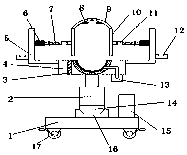
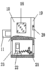
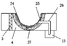
[0030] refer to Figure 1-6 , a new type of head fixation device for ophthalmic examination, comprising a base 1, the four corners of the bottom outer wall of the base 1 are fixed with brake universal wheels 17 by screws, and the top outer wall of the base 1 is fixed with electric control slide rails 16, The top inner wall of the electric control slide rail 16 is slidably connected with a slider 14, and the top outer wall of the slider 14 is fixed with a hydraulic cylinder 2 by screws, and one end of the piston rod of the hydraulic cylinder 2 is fixed with a supporting plate 4 by a bolt, and the supporting plate 4 The outer walls on both sides are fixed with fixed pl...


PUM


Abstract

The invention belongs to the technical field of ophthalmologic instruments, in particular to a novel head fixing device for ophthalmologic examination, and aims at solving the problem of uncomfortableuse when the ophthalmologic examination is performed on a patient by means of the head fixing device. A scheme is proposed, and the head fixing device includes a base, universal wheels with brakes are fixed to the four corners of the bottom outer wall of the base through screws, and an electrically controlled slide rail is fixed to the top outer wall of the base through screws; the top inner wall of the electrically controlled slide rail is slidably connected with a sliding block, and a hydraulic cylinder is fixed to the top outer wall of the sliding block through screws; a support plate isfixed to one end of a piston rod of the hydraulic cylinder through bolts, fixing plates are fixed to the outer walls at both sides of the support plate through screws, the fixing plates are of L-shaped structures, and servo motors are fixed to the outer walls at one sides of the two fixing plates through screws. The head fixing device can move freely, and the height of the head fixing device can be freely adjusted, so that psychology stress of the patient can be reduced when eyes are inspected, thereby avoiding the phenomenon that the scalp is bruised by overhardening strap snaps.

Description

technical field [0001] The invention relates to the technical field of ophthalmic instruments, in particular to a novel head fixation device for ophthalmic examination. Background technique [0002] General examination of the eye, including the examination of the ocular adnexa and anterior segment, the examination of the ocular adnexa includes the examination of the eyelid, conjunctiva, lacrimal apparatus, eyeball position and orbit. Treatment or detection to fix the head, usually by tightening the fixation on both sides, the fixation effect is not obvious and the treatment or detection can not achieve good results. Therefore, adopting effective fixation methods has become the development direction of modern medicine, and often encounters the elderly Some patients, such as children and children, shake their heads from side to side and do not cooperate with the treatment, which affects the normal inspection. [0003] The existing head immobilization device for ophthalmic exa...

Claims


Application Information

Patent Timeline
Patent Type & Authority Applications(China)
IPC IPC(8): A61B90/14A61B3/00
CPCA61B90/14A61B3/00
Inventor 许桂敏
Owner 许桂敏
Learn More