Hard rock ditching machine and hard rock ditching method

A ditching machine and hard rock technology, applied in the field of hard rock ditching machine and hard rock ditching, can solve problems such as unsuitability of roadheaders, achieve the effects of preventing slipping, ensuring stable operation, and increasing friction

Active Publication Date: 2022-06-28
CHINA RAILWAY ENGINEERING EQUIPMENT GROUP CO LTD
View PDF11 Cites 0 Cited by
  • Summary
  • Abstract
  • Description
  • Claims
  • Application Information

AI Technical Summary

Problems solved by technology

[0004] The purpose of the present invention is to provide a hard rock ditching machine to solve the technical problem that the roadheader in the prior art is not suitable for occasions with large slopes

Method used


Image

  • Hard rock ditching machine and hard rock ditching method
  • Hard rock ditching machine and hard rock ditching method
  • Hard rock ditching machine and hard rock ditching method

Examples


Embodiment 1

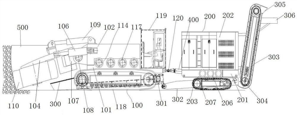
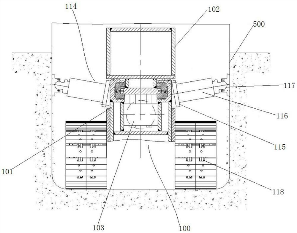
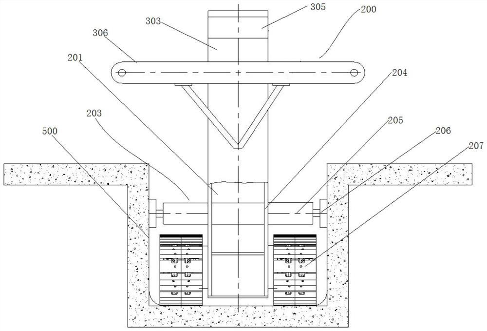
[0043] like figure 1 As shown, the hard rock trencher provided by the present invention includes a front traveling unit 100, a rear traveling unit 200, a telescopic driving device 400 and a muck conveying device, and the front traveling unit 100 is provided with a cutting device for rock breaking and a driving cutting device The swinging cutting cantilever, the rear traveling unit 200 is provided with an energy unit 202 that provides power for the entire trencher. In addition, the front and rear traveling units are also provided with support devices, which are used to support the corresponding side walls of the pipe trench 500 during use. In addition, both ends of the telescopic drive device 400 are respectively connected with the front and rear travel devices, and when the telescopic drive device 400 is stretched, a pushing force or a pulling force is formed between the front and rear travel units. For the convenience of expression, the length direction of the hard rock tren...

Embodiment 2

[0055] The difference between this embodiment and Embodiment 1 is that, in Embodiment 1, four sets of front support devices are provided on the left and right sides of the front chassis. In this embodiment, the number of the front support devices on the left and right sides of the front chassis can be set by yourself, for example, three sets of front support devices are provided on the left and right sides of the front chassis.

Embodiment 3

[0057] The difference between this embodiment and Embodiment 1 is that, in Embodiment 1, three sets of rear support devices are respectively provided on the left and right sides of the rear chassis. In this embodiment, the number of rear support devices on the left and right sides of the rear chassis can be set by yourself, for example, four sets of rear support devices are provided on each of the left and right sides of the rear chassis.


PUM


Abstract

The invention provides a hard rock furrowing machine and a hard rock furrowing method.The hard rock furrowing method comprises the step that the hard rock furrowing machine goes uphill in a pipe ditch, the hard rock furrowing machine comprises a front walking unit and a rear walking unit, a cutting device and a cutting cantilever are arranged on the front walking unit, and an energy unit is arranged on the rear walking unit; supporting devices are arranged on the front walking unit and the rear walking unit respectively, the supporting devices are located on the left side and the right side of the corresponding walking unit, each supporting device comprises a device base fixed to the corresponding walking unit, a telescopic arm is assembled on each device base, and a supporting bottom foot used for being supported to the corresponding side wall of a pipe ditch is arranged at the tail end of each telescopic arm; the hard rock ditcher further comprises a telescopic driving device, the two ends of the telescopic driving device are connected with the front walking unit and the rear walking unit respectively, and the telescopic driving device is used for forming jacking force or traction force between the front walking unit and the rear walking unit in the telescopic process. The hard rock ditcher provided by the invention effectively solves the technical problem that a heading machine in the prior art is not suitable for occasions with large slopes.

Description

technical field [0001] The invention relates to the technical field of roadheaders for digging trenches, in particular to a hard rock trenching machine and a hard rock trenching method. Background technique [0002] When laying the oil and gas pipeline network, it is necessary to dig trenches on the ground and then bury it in the dug trenches. During the construction process, it is sometimes necessary to lay the oil and gas pipeline network in the undulating areas. The geological conditions of these undulating areas are complex. The surface is mostly rock, making trenching difficult. Explosives or breakers are usually used to dig trenches in the prior art, but due to environmental protection and safety issues, the use of explosives is limited. In addition, the method of breaker is a kind of crushing trencher and trenching method disclosed in the Chinese Invention Application Publication No. CN113309162A, but the use of breaker for trenching has low efficiency, which will le...

Claims


Application Information

Patent Timeline
Patent Type & Authority Applications(China)
IPC IPC(8): E02F5/02E02F5/14B62D55/065B62D55/075
CPCE02F5/02E02F5/14B62D55/065B62D55/075
Inventor 叶蕾马永辉李光贾金建贾涛鲁超张雅博
Owner CHINA RAILWAY ENGINEERING EQUIPMENT GROUP CO LTD
Why Eureka
Try Eureka