Building elevator shaft inner mold self-lifting construction method and device

A technology for construction devices and elevator shafts, which is applied in the direction of construction, building structure, formwork/formwork/work frame, etc., to achieve the effect of saving labor costs and reducing work processes

Active Publication Date: 2022-06-28
中化学建设集团有限公司
View PDF8 Cites 0 Cited by
  • Summary
  • Abstract
  • Description
  • Claims
  • Application Information

AI Technical Summary

Problems solved by technology

[0004] In order to overcome the disadvantage of manually cleaning the debris attached to the surface of the mold, the present invention provides a self-elevating construction method and construction device for the inner mold of a building elevator shaft that can fully shake off the debris attached to the surface of the mold without manual cleaning by workers

Method used


Image

  • Building elevator shaft inner mold self-lifting construction method and device
  • Building elevator shaft inner mold self-lifting construction method and device
  • Building elevator shaft inner mold self-lifting construction method and device

Examples


Embodiment 1

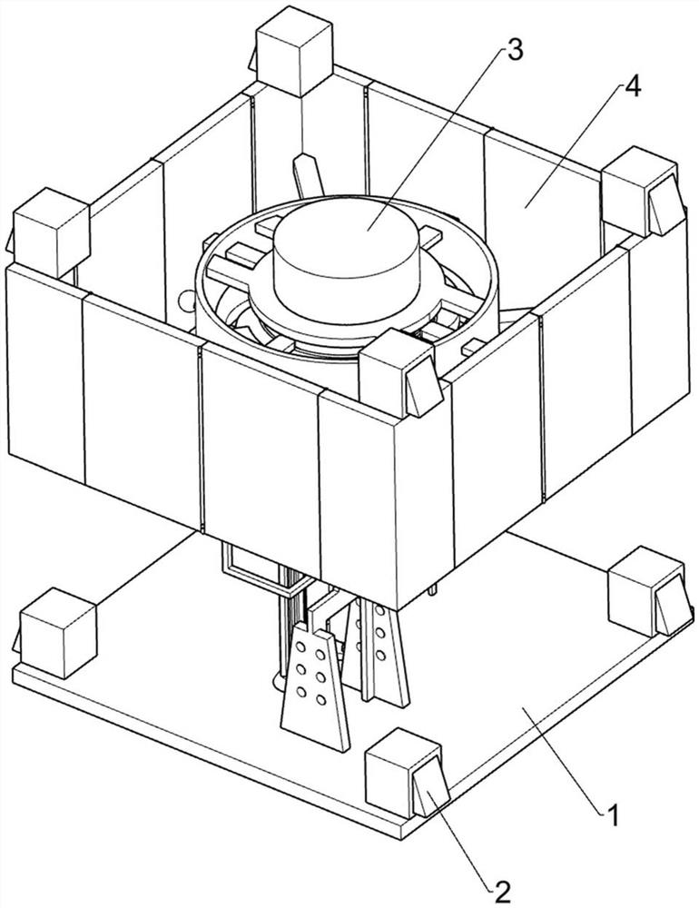
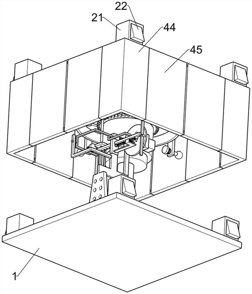
[0030] Self-lifting construction method and construction device of building elevator shaft inner formwork, such as Figure 1-10 As shown, it includes a bottom support plate 1, a support part 2, a climbing part 3, an inner mold shrinking part 4, a driving part 5, a power part 6, a trigger stop part 7 and a lifting part 8, and the bottom support plate 1 is provided with a support Part 2, the top of the bottom support plate 1 is provided with a climbing part 3, the climbing part 3 is provided with an inner mold shrinking part 4, the inner mold shrinking part 4 is also provided with a supporting part 2, a driving part 5 is provided on the climbing part 3, and the bottom part is A power part 6 is provided on the top of the support plate 1 , a trigger stop part 7 is provided on the power part 6 , and a lifting part 8 is provided on the power part 6 .

[0031] The support member 2 includes a hollow sleeve 21, an inclined surface block 22 and a return spring 1 23, four hollow sleeves ...

Embodiment 2

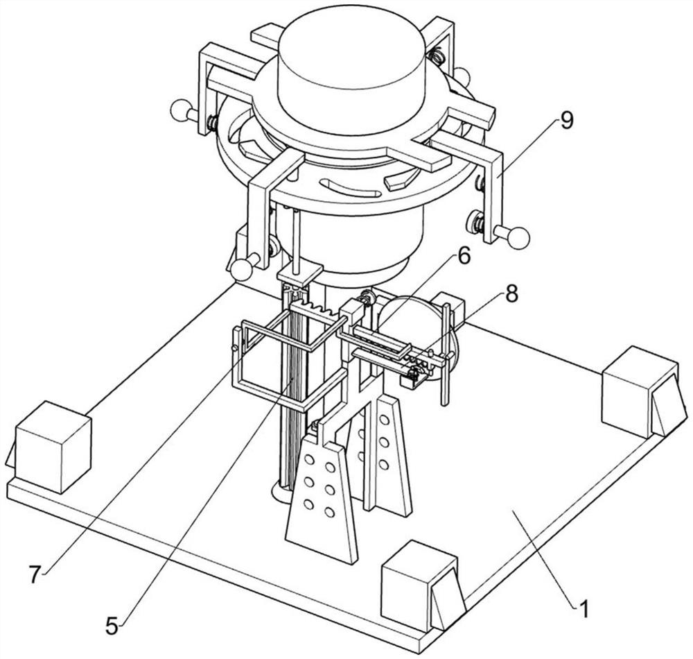
[0044] On the basis of Example 1, as Figure 7 As shown, it also includes an auxiliary blanking part 9, an auxiliary blanking part 9 is provided on the annular guide cylinder 42, and the auxiliary blanking part 9 includes a sloped push bar 91, a driven plate 92, a buffer spring 93, a rubber ball The push rod 94 and the second buffer spring 95, the top of the inclined groove push plate 55 are distributed and welded with four inclined plane push bars 91, the annular guide cylinder 42 is slidably provided with four driven plates 92, and the inclined plane push bars 91 are used to push the The driven plate 92, a buffer spring 93 is connected between the driven plate 92 and the annular guide cylinder 42, the driven plate 92 is slidably connected with a push rod 94 with a rubber ball, and the push rod 94 with a rubber ball is used to impact the folding plate 45. A second buffer spring 95 is connected between the push rod 94 with a rubber ball and the driven plate 92.

[0045] When ...


PUM


Abstract

The invention relates to the field of building construction, in particular to a building elevator shaft inner mold self-lifting construction method and device. According to the self-lifting construction method and device for the building elevator shaft inner mold, manual cleaning of workers is not needed, and chippings attached to the surface of the mold can be automatically and fully shaken off. The self-lifting construction device comprises a bottom supporting plate, a supporting component and the like. And a supporting part is arranged on the bottom supporting plate. Through cooperation of devices such as an inner mold shrinkage component and a driving component, concrete chippings attached to the surfaces of the folding plate and the L-shaped plate are fully shaken off, the folding plate and the L-shaped plate do not need to be manually cleaned by workers in the subsequent process, the working process is greatly shortened, and the working efficiency is improved. And meanwhile, shake-off of the concrete chippings is completed in the rising process of the folding plate and the L-shaped plate, the time is effectively utilized, workers do not need to spend extra time to clean the concrete chippings, and the purposes of saving time and saving labor cost are achieved.

Description

technical field [0001] The invention relates to the field of building construction, in particular to a self-lifting construction method and a construction device of an inner formwork of a building elevator shaft. Background technique [0002] The elevator shaft is the hoistway where the elevator is installed. During the design process, since the architect has considered the size of the elevator that needs to be selected in advance, the size of the elevator shaft during the pouring process is determined accordingly, and the elevator shaft belongs to the bottom. In order to speed up the construction efficiency of the elevator shaft, the construction personnel in the industry generally use the device with the self-lifting function of the mold, which is convenient to greatly shorten the time of mold assembly and ensure that the specifications and dimensions of the inner wall of the elevator shaft are the same. . [0003] The existing elevator shaft device with the function of s...

Claims


Application Information

Patent Timeline
Patent Type & Authority Applications(China)
IPC IPC(8): E04G11/28E04G19/00
CPCE04G11/28E04G19/006
Inventor 蔡涛程小龙
Owner 中化学建设集团有限公司
Why Eureka
Try Eureka