Socket for electrical parts

a technology for electrical parts and sockets, which is applied in the direction of coupling device connections, engagement/disengagement of coupling parts, electrical apparatus, etc. it can solve the problems of affecting the work efficiency of the electrical circuit, affecting the electrical conductivity of the spherical terminal surface, and limiting the material selection, etc., to achieve easy formation of contact pins, reduce work process, and eliminate defects or drawbacks

Inactive Publication Date: 2007-05-01
ENPLAS CORP
View PDF3 Cites 8 Cited by
  • Summary
  • Abstract
  • Description
  • Claims
  • Application Information

AI Technical Summary

Benefits of technology

[0009]An object of the present invention is to substantially eliminate defects or drawbacks encountered in the prior art mentioned above and to provide a socket for an electrical part capable of easily forming contact pins with a reduced working process and with increased number of materials selectively usable, reducing movable range of the contact pin and ensuring electrical connection between the contact pin and a spherical terminal.

Problems solved by technology

However, in such conventional structure of the contact pins, since the contact pins are formed by punching out the plate and then bending the punched out plate member, these workings involve many working steps, and in addition, in the bending working, it is obliged to select a material for the plate member that can endure the bending working, which limits the materials to be selected.
For example, as such material, beryllium copper is generally utilized, but this material has a fear of being deteriorated in elasticity because of influence of heat.
In addition, the contact surface of the contact pin is contacted in a surface-to-surface fashion to the spherical terminal to thereby establish electrical connection, and then, there is a fear of making worse the electrical conductivity in a case where the surface of the spherical terminal is coarse.

Method used


Image

  • Socket for electrical parts
  • Socket for electrical parts
  • Socket for electrical parts

Examples


Embodiment Construction

[0051]One preferred embodiment of the present invention will be described hereunder with reference to the accompanying drawings. Further, it is to be noted that terms “upper”, “lower”, “right”, “left” and the like terms are used herein with reference to the illustration of the drawings or in generally usable state of the socket of the present invention.

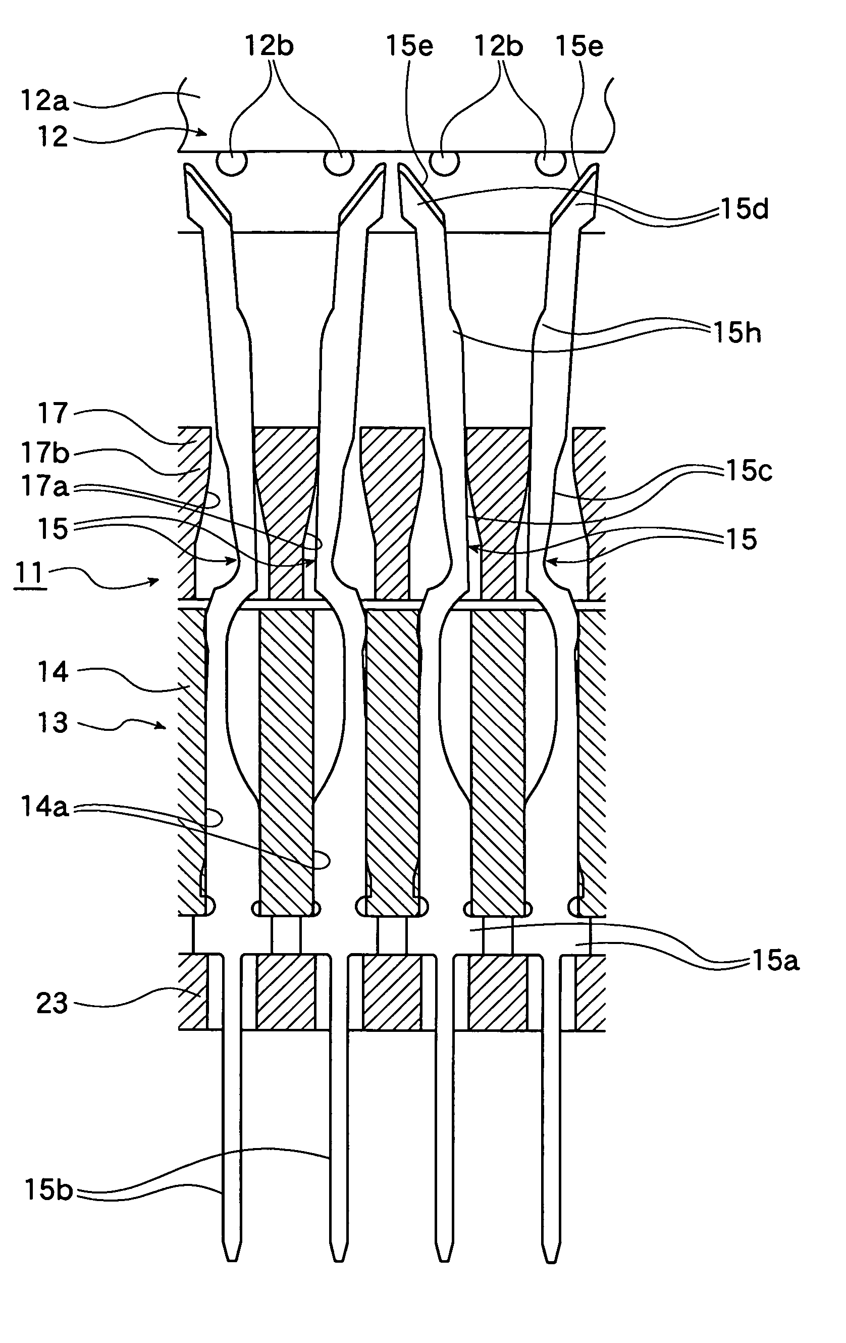
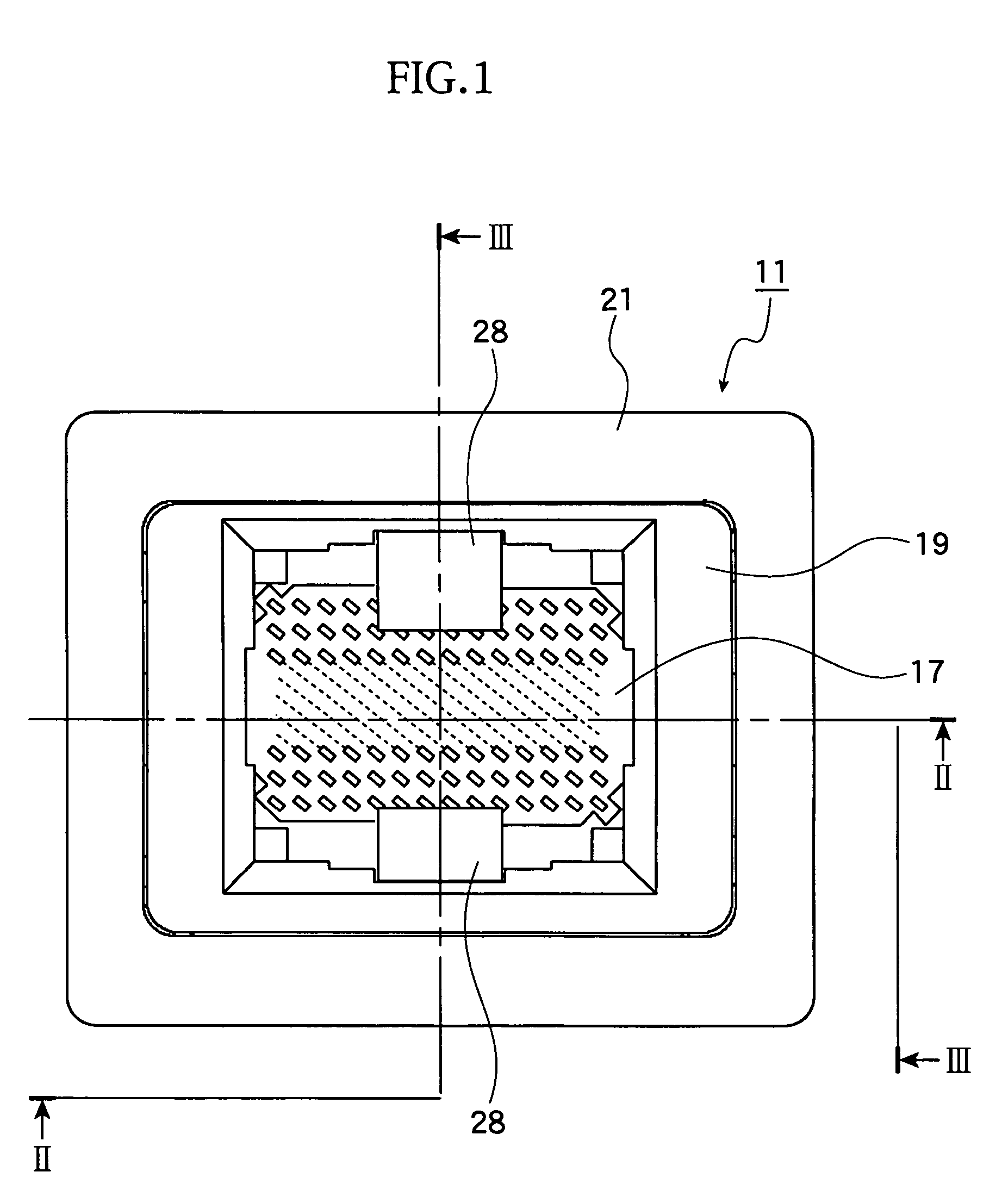
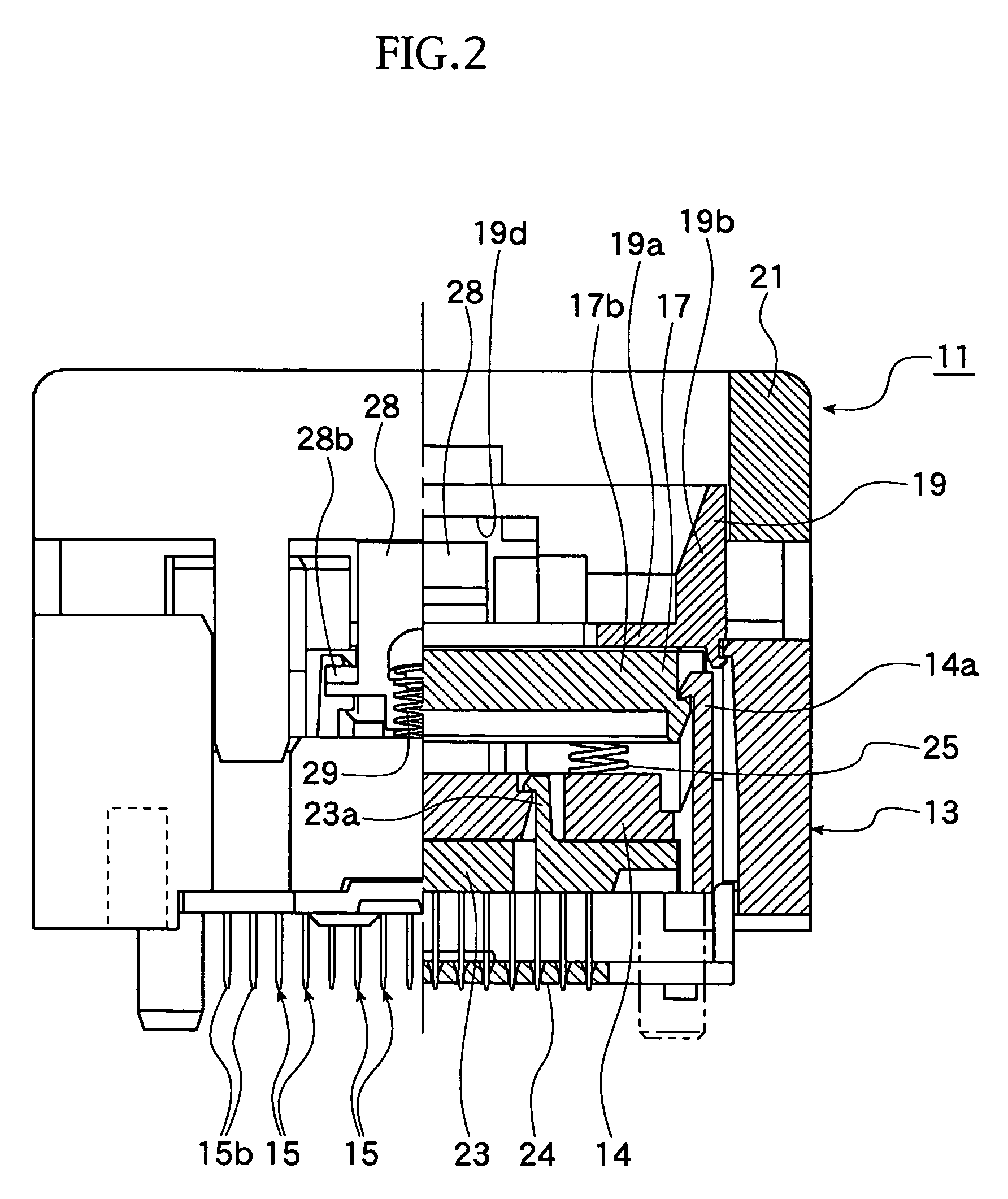
[0052]With reference to FIGS. 1 to 16, reference numeral 11 denotes an IC socket as a socket for an electrical part, to which an IC package as an electrical part is accommodated to thereby establish an electrical connection between the IC package 12 and a printed circuit board, not shown, through the IC socket 11. According to such electrical connection, a performance test for the IC package 12 is carried out.

[0053]The IC package 12 is, as shown in FIGS. 6 and 7, so-called a BGA (Ball Grid Array) type, in which a number of ball-shaped solder ball 12b as spherical terminals are arranged to the lower surface of a square package body 12a...


PUM


Abstract

A socket for an electrical part includes a socket body formed with an accommodation portion in which an electrical part having spherical terminals is accommodated and contact pins arranged to the socket body to be contacted to and separated from the terminals such as solder balls, respectively, and a movable member for elastically deforming the contact pins in a horizontal direction. Each of the contact pins has one elastic piece in form of plate having conductivity and elasticity so as to be elastically deformable along a plate surface direction by the movement of the movable member. The contact pin has a contact portion in form of plate formed at an upper portion of the elastic piece, and the contact portion has a side edge portion which is contacted to or separated from a side surface of the spherical terminal.

Description

BACKGROUND OF THE INVENTION[0001]1. Field of the Invention[0002]The present invention relates to a socket for an electrical part accommodating an electrical part such as semiconductor device (which may be called hereinlater “IC package”).[0003]2. Related Art[0004]A conventional example of such a socket for an electrical part is, for example, disclosed in Japanese Patent Application Laid-open Publication No. HEI 8-88063 as an IC socket. This IC socket has a socket body to which a number of contact pins are arranged, and contact portions of these contact pins contact side surfaces of solder balls as spherical terminals of an IC package.[0005]The contact pins are formed from a sheet of plate by punching and then bending the plate so that the contact pin has, at its upper end portion, a contacting surface having wide area so as to abut against the side surface of the solder ball when assembled.[0006]The contact pins of the structure mentioned above are divided into two or three groups, ...

Claims


Application Information

Patent Timeline
Patent Type & Authority Patents(United States)
IPC IPC(8): H01R13/62
CPCH05K7/1069H01R33/76
Inventor HAYAKAWA, KENJI
Owner ENPLAS CORP
Why Eureka
Try Eureka