Multifunctional integrated power tower

An integrated technology for power poles and towers, applied in the field of multifunctional integrated power poles and towers, which can solve problems such as breakage, easy toppling of power poles and towers, and threat of power poles and towers

Active Publication Date: 2022-06-28
江苏银河钢杆有限公司
View PDF5 Cites 0 Cited by
  • Summary
  • Abstract
  • Description
  • Claims
  • Application Information

AI Technical Summary

Problems solved by technology

[0005]In order to overcome the inability to protect the operator, there is a safety risk, and when it encounters strong wind for a long time, it exceeds the ultimate breaking force of the power tower. The power pole tower ...

Method used


Image

  • Multifunctional integrated power tower
  • Multifunctional integrated power tower
  • Multifunctional integrated power tower

Examples


Embodiment 1

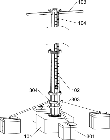
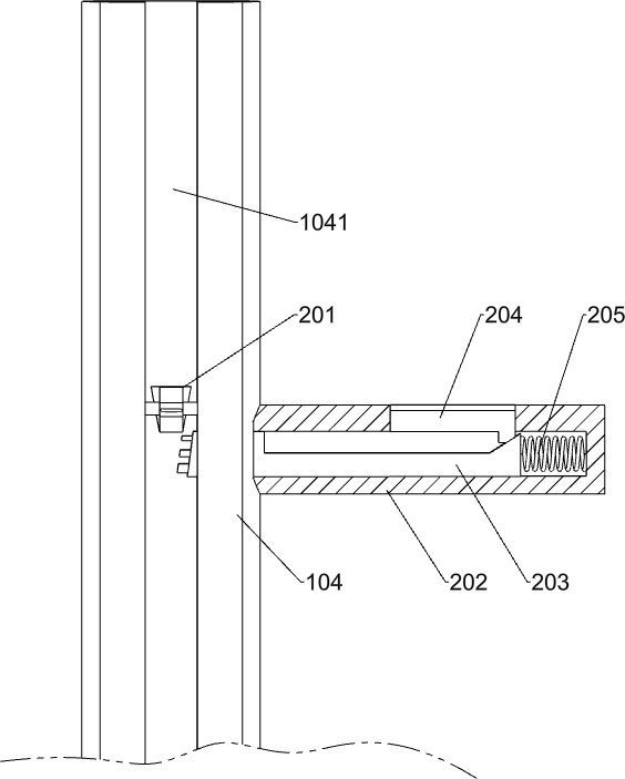
[0029] A multifunctional integrated power tower, such as Figure 1-Figure 9 As shown, a first base 101 is included, and rod bodies 102 are fixed on the first base 101. Several rod bodies 102 are provided and arranged vertically. Every two rod bodies 102 are fixedly connected by screws and nuts. The left and right sides of the inner upper part of the rod body 102 are provided with first limit holes 1021 for installation, and the left and right sides of the upper part of the uppermost rod body 102 are fixedly connected with a cable support frame 103. The cable support frame 103 is provided with overhead cables. A climbing frame 104 is fixedly connected to the front side of each rod body 102 through a connecting block. The climbing frame 104 is used to facilitate the operator to climb. The climbing frame 104 is provided with a first chute 1041 and the climbing frame 104 is There are several second limit holes 1042 for slowing down the operator's tendency to fall. The second limit...

Embodiment 2

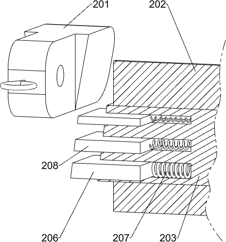
[0033] On the basis of Example 1, as Figure 1-Figure 5 As shown, the anti-fall mechanism includes an anti-fall sliding block 201, the anti-fall sliding block 201 is slidably connected to the climbing frame 104, the anti-fall sliding block 201 is located in the first chute 1041, and the left and right sides of the climbing frame 104 are fixedly connected There are several climbing foot frames 202, and the climbing foot frames 202 on both sides are staggered. The climbing foot frames 202 are slidably connected with a first sliding deceleration block 203 for slowing down the operator's falling speed. There are three chutes on the block 203, and a pedaling sliding block 204 is slidably connected to the climbing foot frame 202. Several pedaling sliding blocks 204 are squeezed and fitted with the adjacent first sliding deceleration blocks 203 respectively for preventing falling and sliding. The block 201 slides, and a first spring 205 is fixed between the several first sliding dece...

Embodiment 3

[0047] On the basis of Example 2, as Figure 6-Figure 8 As shown, the anti-tipping mechanism includes a second base 301, four second bases 301 are provided, and four second bases 301 are slidably connected with anti-dumping sliding blocks 302 for sensing the inclination angle of the rod body 102. Connecting rods 303 are spherically connected to each of the anti-overturning sliding blocks 302, and an octagonal fixing frame 304 is fixedly connected to the lowermost rod body 102. Two fifth springs 305 are fixed between the dumping sliding blocks 302 and the adjacent second bases 301 respectively, and the eight fifth springs 305 are used to decelerate the adjacent anti-dumping sliding blocks 302 and slow down the inclination of the rod body 102 . Angle, the second base 301 is slidably connected with an anti-dumping component, and the anti-dumping component is used to further decelerate the adjacent anti-dumping sliding blocks 302 .

[0048] The anti-overturning assembly includes ...


PUM


Abstract

The invention relates to the technical field of electric power engineering, in particular to a multifunctional integrated electric power tower. The technical problems that a traditional electric power pole tower cannot protect operators, safety risks exist, and when the traditional electric power pole tower is blown by strong wind for a long time, the limit breaking force of the electric power pole tower is exceeded, and surrounding buildings and crowds are threatened are solved. According to the technical scheme, the multifunctional integrated power tower comprises a first base; a plurality of rod bodies are fixedly connected to the first base, a climbing frame is fixedly connected to the front side face of each rod body through a connecting block, an anti-falling mechanism is slidably connected into each climbing frame, and an anti-toppling mechanism is fixedly connected to the lowest rod body. The falling trend of an operator is slowed down through the anti-falling mechanism, the operator can hold or step on a certain climbing pedal frame again at a low speed, injury is avoided, the device adapts to different inclination degrees of a rod body through the anti-toppling mechanism, and the situation that the toppling rod body hurts the operator or damages a building is avoided.

Description

technical field [0001] The invention relates to the technical field of electric power engineering, in particular to a multifunctional integrated electric power tower. Background technique [0002] Towers are supports used to support transmission lines in overhead distribution lines, and one of the basic equipment in overhead distribution lines. Most of them are made of steel or reinforced concrete. With the vigorous development of 5G technology in my country, more and more 5G base stations have been put into use, and people have erected 5G base stations on power towers, sharing a tower for power and communication, which can not only solve the problem of electricity, but also solve the problem of signal coverage. [0003] When the existing power tower is repaired, the operator needs to climb to the height of the power tower for maintenance. In the event of an accident that causes the operator to fall, the existing power tower cannot provide protection for the operator, and the...

Claims


Application Information

Patent Timeline
IPC IPC(8): E04H12/00E04H12/22E04G21/32E06C7/08E06C9/08F16F15/067
CPCE04H12/00E04H12/22E04G21/3204E06C7/08E06C9/08F16F15/067
Inventor 张建伟
Owner 江苏银河钢杆有限公司
Why Eureka
Try Eureka