Determination system for friction sensitivity of energetic material
A technology of friction sensitivity and measurement system, which is applied in the direction of analyzing materials, material inspection products, measuring devices, etc., can solve the problems of poor stability of pressurized parts, affecting test accuracy, and incompletely accurate test results, so as to reduce the impact and ensure The effect of precision
- Summary
- Abstract
- Description
- Claims
- Application Information
AI Technical Summary
Problems solved by technology
Method used
Image
Examples
Embodiment 1
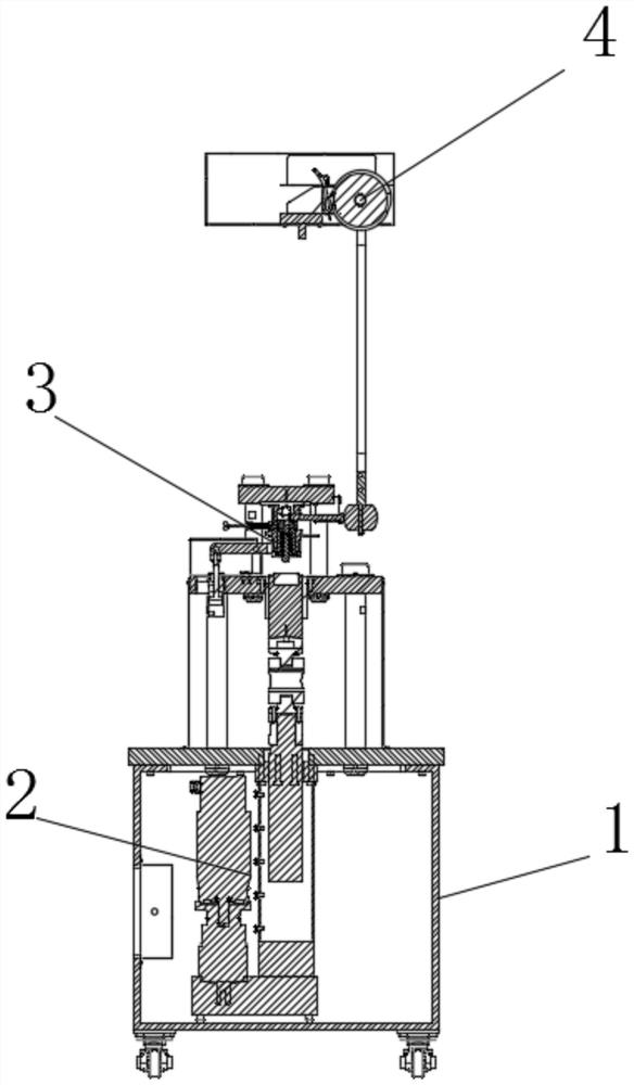
[0030] like figure 1 As shown, in this embodiment, a measurement system for friction sensitivity of energetic materials includes a frame 1, a test structure 3 arranged on the frame 1 and capable of clamping the test piece 5, a test structure 3 arranged above the test structure 3 and used for For the striking structure 4 that applies striking force to the test piece 5 , the test structure 3 is slidably provided with a striker 322 that can be aligned with the test piece 5 and is drive-connected to the striking structure 4 .
[0031] When the test piece 5 needs to be tested, the test piece 5 is clamped by the test mechanism 3, so that the test piece 5 is subjected to a constant pressure, and a striking force is applied to the striker 322 through the striking structure 4, so that the striker 322 hits the test piece 5. , the sliding friction occurs between the test piece 5 and the test mechanism 3 , and the explosion probability of the test piece 5 is observed to characterize the f...
Embodiment 2
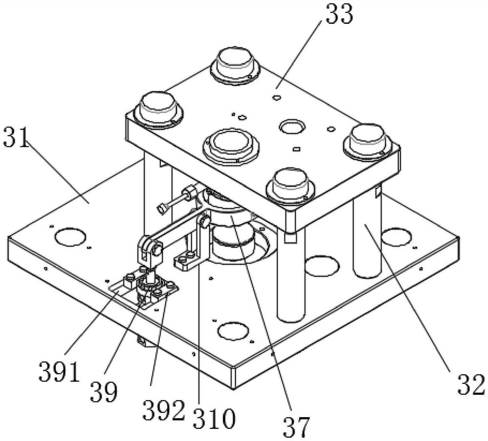
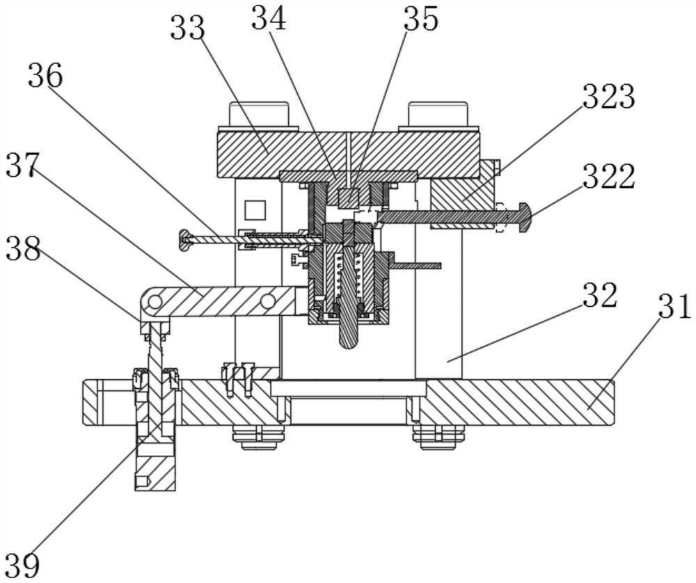
[0035] like figure 2 , image 3 , Figure 4 , Figure 5 As shown, on the basis of the above embodiment, in this embodiment, the test structure 3 includes an instrument body 312 arranged in the rack 1 and having a through hole, an upper top post 35 arranged at one end of the through hole, and The punch 317 is slidably arranged at the other end of the through hole and can clamp the test piece 5 with the upper top column 35. The side surface of the instrument body 312 is provided with an opening communicating with the through hole, and the draw rod 322 is aligned with the instrument body 312. The opening of the frame 1 is provided with a driving structure 2 for driving the punch 317 to move.
[0036] The test piece 5 is clamped by the upper top column 35 and the punch 317 to keep the test piece 5 fixed during the test. The instrument body 312 can relatively isolate the test piece 5 from the surrounding environment, so that the test piece 5 can only enter and exit through the...
Embodiment 3
[0041] like Figure 4 , Figure 5 As shown, on the basis of the above embodiment, in this embodiment, a bracket 315 is arranged in the instrument body 312, and a stepped through hole with a small hole facing upward is arranged in the bracket 315, and one end of the punch 317 is connected to the The small holes of the stepped through holes are installed together, and the large holes of the stepped through holes are connected with a bracket nut 319 through threads. One end of the punch 317 passes through the bracket nut 319. There is a spring 316 sleeved on the punch 317 in the large hole of the .
[0042] The punch 317 can be installed in cooperation with the small hole of the stepped through hole, which can guide and limit the punch 317, control the moving direction of the punch 317, and prevent the punch 317 from moving and shaking at will and affecting the stability of the test piece 5. sex.
[0043] The bracket nut 319 can support and limit the shaft shoulder on the punc...
PUM
 Abstract
Description
Claims
Application Information
 - R&D
- Intellectual Property
- Life Sciences
- Materials
- Tech Scout
- Unparalleled Data Quality
- Higher Quality Content
- 60% Fewer Hallucinations
Browse by: Latest US Patents, China's latest patents, Technical Efficacy Thesaurus, Application Domain, Technology Topic, Popular Technical Reports.
© 2025 PatSnap. All rights reserved.Legal|Privacy policy|Modern Slavery Act Transparency Statement|Sitemap|About US| Contact US: help@patsnap.com


