Supercharge Your Innovation With Domain-Expert AI Agents!

Microlens and filter layer for emission control with curved display

A technology of microlenses and filters, applied in lenses, instruments, optics, etc., can solve problems such as low efficiency

Pending Publication Date: 2022-06-28
SHARP KK
View PDF5 Cites 0 Cited by
  • Summary
  • Abstract
  • Description
  • Claims
  • Application Information

AI Technical Summary

Problems solved by technology

Micro-louvered films are effective but inefficient and only work on one optical axis (such as the axis perpendicular to the display surface of the flat panel)

Method used


Image

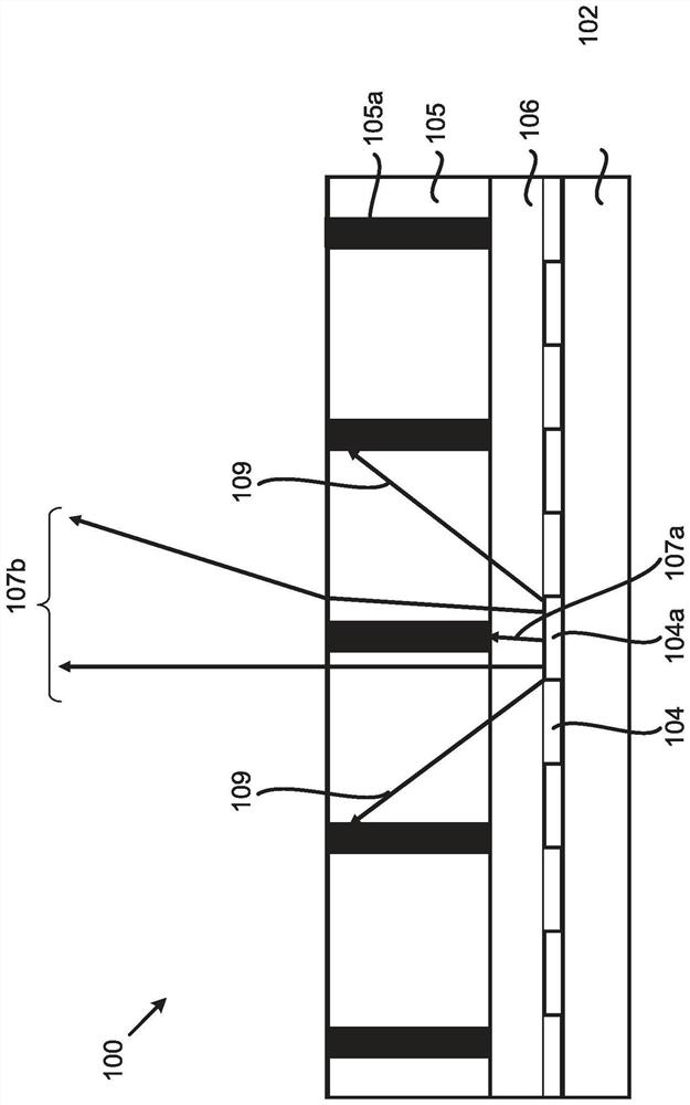
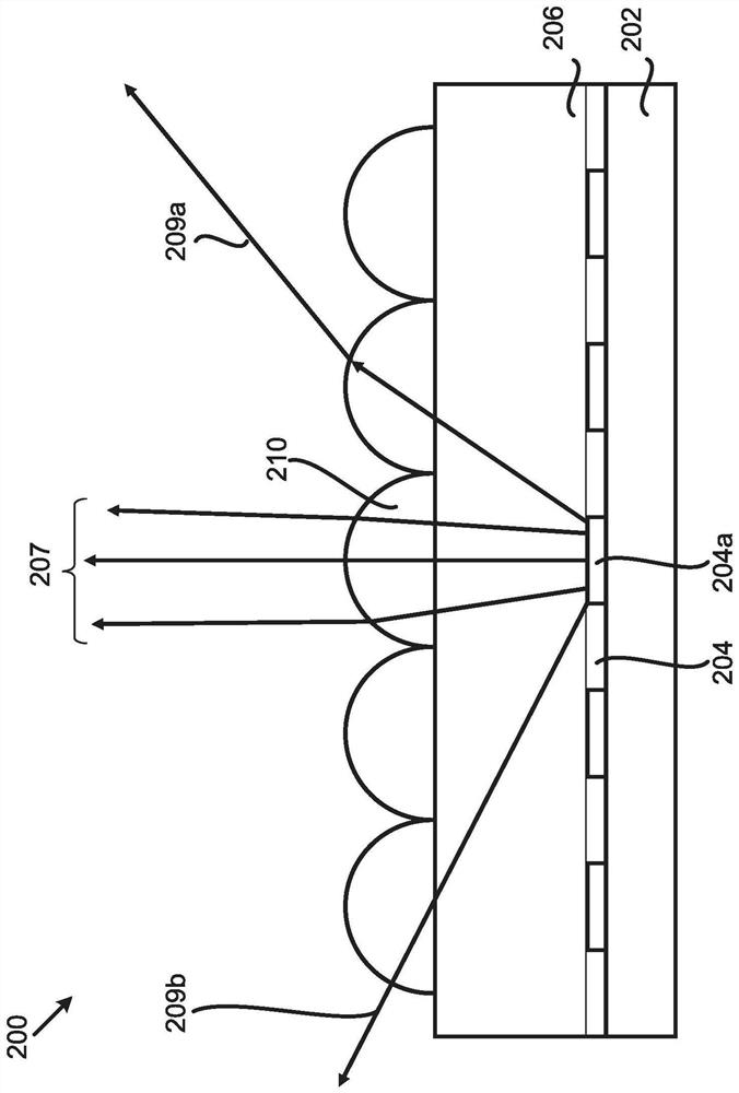
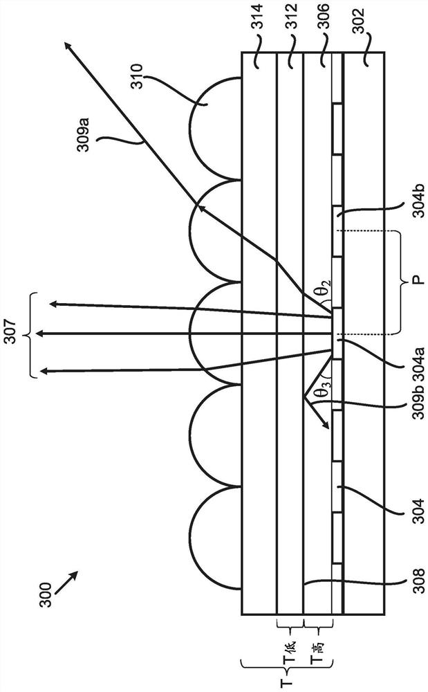
  • Microlens and filter layer for emission control with curved display
  • Microlens and filter layer for emission control with curved display
  • Microlens and filter layer for emission control with curved display

Examples


Embodiment Construction

[0045] The following disclosure contains specific information related to example implementations in this disclosure. The drawings in this disclosure and their accompanying detailed implementations are for example implementations only. However, the present disclosure is not limited to only these example implementations. Other modifications and implementations of the present disclosure will occur to those skilled in the art.

[0046] The same or corresponding elements in the figures may be represented by the same or corresponding reference numerals unless otherwise indicated. Furthermore, the drawings and illustrations in this disclosure are generally not to scale and are not intended to correspond to actual relative dimensions.

[0047] For purposes of consistency and ease of understanding, in the example figures, similar components may be identified by the same reference numerals (although in some examples, not shown). However, features in different implementations may vary...


PUM


Abstract

A light emitting structure includes: a pixel layer having at least one sub-pixel; a microlens layer having at least one microlens, the at least one microlens aligned with the at least one sub-pixel to provide a steadily restricted on-axis emission profile along the on-axis direction; and a first layer of filler material and a second layer of filler material between the pixel layer and the microlens layer, an interface between the first layer of filler material and the second layer of filler material configured to reflect a portion of the off-axis emission from the at least one sub-pixel by total internal reflection (TIR).

Description

technical field [0001] The present disclosure relates generally to microlenses and filter layers for emissive devices, and in particular for curved automotive displays. In particular, the present disclosure aims to improve the narrowly defined emission profile of curved displays. Background technique [0002] Screens are becoming more common in vehicles such as automobiles and provide functions such as information, entertainment and navigation. The potential market is huge, and display technology offers automakers a way to differentiate their products. This is a challenging environment as displays are subject to space constraints, ambient heat, electrical interference, and ambient lighting ranging from direct sunlight to near total darkness. [0003] Displays in vehicles (eg curved displays in the dashboard area of ​​a vehicle) are becoming more and more common. However, unlike displays used within stationary enclosures (eg, homes, offices, etc.), curved displays in vehic...

Claims


Application Information

Patent Timeline
IPC IPC(8): H01L33/58H01L33/60H01L27/15
CPCH01L33/58H01L33/60H01L27/153G02B5/28G02B3/005G02B5/22G02B5/0257H10K50/85H10K50/858
Inventor 威廉·弗雷德里克·史密斯大卫·詹姆斯·蒙哥马利
Owner SHARP KK
Features
  • R&D
  • Intellectual Property
  • Life Sciences
  • Materials
  • Tech Scout
  • Unparalleled Data Quality
  • Higher Quality Content
  • 60% Fewer Hallucinations
Learn More