Rotary electrostatic adsorption driver
An electrostatic adsorption and driver technology, applied in the direction of electrostatic motor, electrostatic generator/motor, generator/motor, etc., can solve the problems of complex driver structure, slow driving movement speed, complex driving structure, etc., and achieve easy off-line movement, The effect of high energy conversion efficiency and simple driving structure
- Summary
- Abstract
- Description
- Claims
- Application Information
AI Technical Summary
Problems solved by technology
Method used
Image
Examples
Embodiment 1
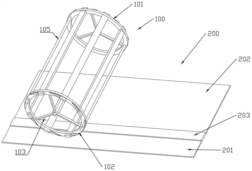
[0043] This embodiment provides a rotary electrostatic adsorption driver 100, see Figure 1 to Figure 6 It includes: a cylindrical driver body formed by a first outer frame 101 and a second outer frame 102 and a plurality of electrodes; both the first outer frame 101 and the second outer frame 102 have supporting surfaces in the circumferential direction, and their bodies also have holes 108; the two ends of the electrodes are inserted into the holes 108 of the first outer frame 101 and the second outer frame 102 respectively and are fixed, and the number of electrodes is multiple and evenly distributed in the first outer frame 101 and the second outer frame 102 in the circumferential direction between; the power supply assembly, which can supply power to the electrodes; the driver body is placed on the support plane 200, and there is no contact between the electrodes and the support plane 200, that is, the driver body is on the support plane 200 through the two support surface...
Embodiment 2
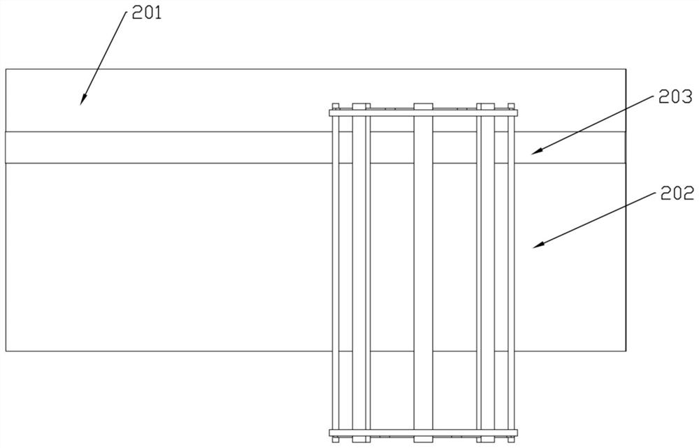
[0053] In addition to the content of the previous embodiment, this embodiment also provides a rotary electrostatic adsorption driver 100, specifically an embodiment in which power is supplied in the form of positive and negative electrodes of a power supply set on a support plane, please refer to the appendix of the description. Figure 1-3 .
[0054] The power supply assembly includes a power supply first stage 201 on the support plane 200, a power supply second pole 202 and a rail 203, and the power supply first stage 201 and the power supply second pole 202 are located on both sides of the rail 203, for example, the power supply first stage 201 is The positive pole, the second pole 202 of the power supply is the negative pole, the first outer frame 101 corresponds to the first stage 201 of the power supply, and the electrode corresponds to the second pole 202 of the power supply and is at least partially above the second pole 202 of the power supply;
[0055] The first oute...
Embodiment 3
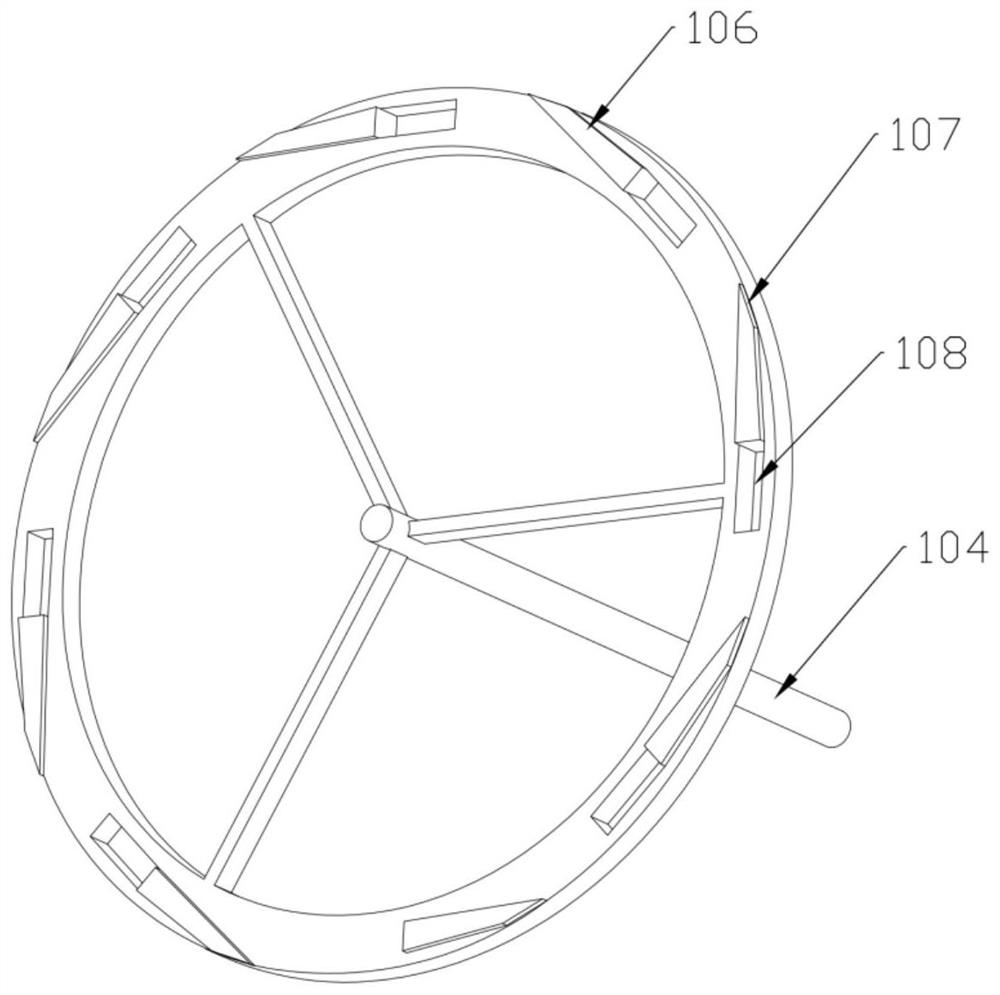
[0058] In addition to the content of the previous embodiment, this embodiment also provides a rotary electrostatic adsorption driver 100, which further defines the conductive structure. See attached manual image 3 .
[0059] The conductive sheet 106 is located on the side of the first outer frame 101 . One end of the conductive sheet 106 is a contact surface 107 formed at the edge of the circumferential support surface of the first outer frame 101 , and the other end is located at the edge of the hole 108 .
[0060] Specifically, in Figure 1-3 , the conductive sheet 106 is located on the side of the first outer frame 101 in the form of a deflection angle, and the end of the electrode is connected to the edge of the circumferential support surface of the first outer frame 101. The advantage of this arrangement is that the electrode is connected to the power supply through the conductive sheet 106. When the first stage 201 is connected, there is a high distance between the e...
PUM
 Abstract
Description
Claims
Application Information
 - R&D
- Intellectual Property
- Life Sciences
- Materials
- Tech Scout
- Unparalleled Data Quality
- Higher Quality Content
- 60% Fewer Hallucinations
Browse by: Latest US Patents, China's latest patents, Technical Efficacy Thesaurus, Application Domain, Technology Topic, Popular Technical Reports.
© 2025 PatSnap. All rights reserved.Legal|Privacy policy|Modern Slavery Act Transparency Statement|Sitemap|About US| Contact US: help@patsnap.com


