Abdominal roller

A technology of abdominal health wheels and rollers, which is applied in the direction of shafts and bearings, elastic resistance devices, gymnastics equipment, etc., and can solve the problem of easy damage of internal springs and related parts, poor user experience and safety, and affects the left and right sides of the abdominal health wheel Balance and other issues, to achieve the effect of reducing production costs, improving user experience, and improving use safety

Active Publication Date: 2022-07-01
金华市舒格科技有限公司
View PDF7 Cites 0 Cited by
  • Summary
  • Abstract
  • Description
  • Claims
  • Application Information

AI Technical Summary

Problems solved by technology

[0002] Chinese patent document CN215691381U discloses a mechanical rebound abdominal wheel that can prevent reverse rotation, which can solve the problem of the rebound abdominal wheel in the past. The problem that the internal spring and related parts are easily damaged due to the reverse phenomenon
[0003]1) The torsion spring mechanism used to realize the rebound function and the stroke positioning mechanism used to realize the anti-reverse and fixed stroke functions are independently designed on the main body of the roller On both sides of the inside, this leads to not only complex structure, high production cost, inconvenient installation, but also poor compact structure, which is not conducive to saving space;
[0004]2) The torsion spring mechanism is set on one side of the main body of the roller, that is, on the side away from the center of the main body of the roller. When the torsion spring mechanism is stretched, or when the abdominal health wheel is retracted backward to make the torsion spring mechanism rebound, the center of gravity of the force from the torsion spring mechanism on the abdominal wheel is biased to the side of the product, which greatly affects the health. The left and right balance of the abdominal wheel during use, the user experience and safety are not good

Method used


Image

  • Abdominal roller
  • Abdominal roller
  • Abdominal roller

Examples


Embodiment Construction

[0034] The present invention will be further described in detail below with reference to the embodiments given in the accompanying drawings.

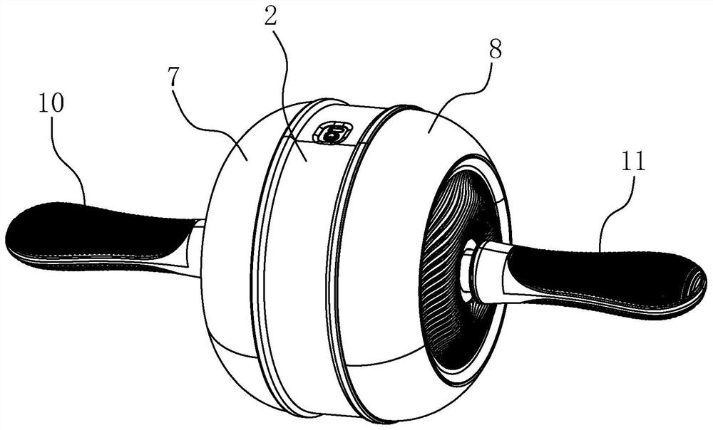
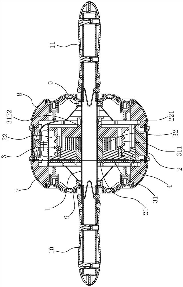
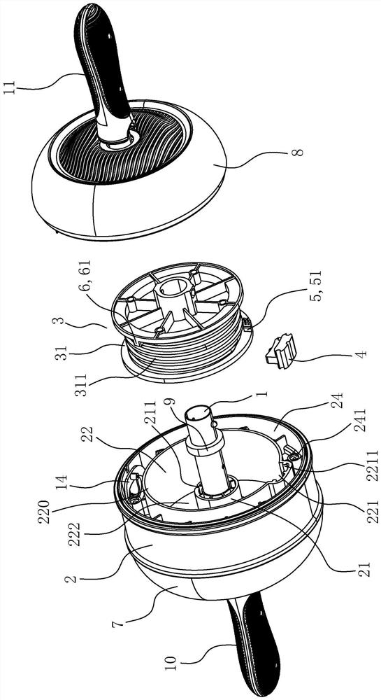
[0035] like Figure 1 to Figure 12 As shown, an abdominal fitness wheel described in this embodiment includes a central shaft 1 , a roller body 2 and a spring mechanism 3 . The roller body 2 has a center sleeve 21 and a cavity 22 which is concentric with the center sleeve 21 and is located on the outer periphery of the center sleeve 21 , and the roller body 2 is rotatably pivoted to the center shaft 1 through the center sleeve 21 , that is to say , the roller body 2 can rotate relative to the central axis 1 . The spring mechanism 3 is installed in the cavity 22 , and the spring mechanism 3 includes a spring barrel 31 and a spring 32 arranged in the spring barrel 31 . One end of the spring barrel 31 is sheathed on the central shaft 1 and is fixedly connected with it, and the other end is sheathed on the central sleeve 21 and is in clea...


PUM


Abstract

An abdominal roller comprises a center shaft, a roller body and a spring mechanism. The roller main body is provided with a central sleeve and an accommodating cavity, and is pivoted to the central shaft through the central sleeve; the spring mechanism is installed in the containing cavity and comprises a spring barrel and a clockwork spring. One end of the spring barrel sleeves the central shaft and is fixedly connected with the central shaft, and the other end sleeves the central sleeve and is in clearance fit with the central sleeve; the clockwork spring is located on the axial center face of the roller body, one end of the clockwork spring is fixed to the spring barrel, and the other end of the clockwork spring is fixed to the center sleeve. A spiral sliding groove is formed in the outer circumferential wall of the spring barrel, an axial sliding groove is formed in the inner circumferential wall of the containing cavity, one end of the stroke positioning piece is embedded into the axial sliding groove, the other end of the stroke positioning piece is embedded into the spiral sliding groove, and when the roller body rotates, the stroke positioning piece slides in the spiral sliding groove and the axial sliding groove. The device further comprises a first limiting mechanism and a second limiting mechanism. The structure is simple and compact, the spring acting force on the two sides of the wheel body is uniform during use, the balance and safety are good, and the user experience feeling is good.

Description

technical field [0001] The invention relates to fitness equipment, in particular to an abdominal fitness wheel. Background technique [0002] Chinese patent document CN215691381U discloses a mechanical rebound belly wheel that can prevent reverse rotation. question. However, the abdominal health wheel designed by this patent also has the following defects, specifically: [0003] 1) The torsion spring mechanism used to realize the rebound function and the stroke positioning mechanism used to realize the anti-reverse and fixed stroke functions are designed separately and independently on both sides of the roller body, which leads to the complex structure of the abdominal wheel. The production cost is high, the installation is inconvenient, and the compactness of the structure is also poor, which is not conducive to saving space; [0004] 2) The torsion spring mechanism is arranged on the inner side of the roller body, that is, it is deviated from the center of the roller bo...

Claims


Application Information

Patent Timeline
Patent Type & Authority Applications(China)
IPC IPC(8): A63B22/20A63B23/02A63B21/02F16C13/00
CPCA63B22/201A63B23/0205A63B21/02F16C13/00
Inventor 周金娥
Owner 金华市舒格科技有限公司
Why Eureka
Try Eureka