Automatic wire arranging device

A technology of automatic wire arrangement and take-up device, applied in the field of wire rope winding equipment, can solve the problems of uneven collection, disorderly arrangement of take-up wires, etc., and achieve the effects of fast wire-receiving process, improving production efficiency and saving production costs.

Pending Publication Date: 2022-07-01
多普勒电梯股份有限公司
View PDF0 Cites 0 Cited by
  • Summary
  • Abstract
  • Description
  • Claims
  • Application Information

AI Technical Summary

Problems solved by technology

[0004] The purpose of the present invention is to provide an automatic wire arrangement device to solve the problems of chaotic arrangement and uneven collection of wires proposed in the above background technology

Method used


Image

  • Automatic wire arranging device
  • Automatic wire arranging device
  • Automatic wire arranging device

Examples


Embodiment 1

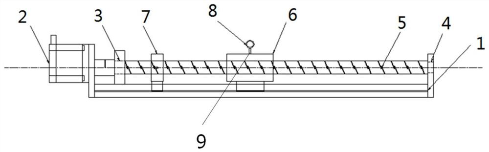
[0022] see Figure 1 to Figure 3 , an automatic arranging device, including a bracket 1 and a lateral movement device; a rotating motor 2 is provided on one side of the bracket 1, the rotating motor 2 and the bracket 1 are fixed and installed by bolts, and the output end of the rotating motor 2 is connected to the shaft through a coupling. The lateral moving device is connected; a mounting seat is provided on the bracket 1, and the mounting seat includes a first mounting seat 3 and a second mounting seat 4; a first mounting seat 3 is provided on the side close to the rotating motor 2, A first installation hole is arranged in the middle, a second installation seat 4 is arranged at one end away from the rotating motor 2, and a second installation hole is arranged in the middle of the second installation seat 4, and the lateral movement device is rotatably installed in the first installation hole and the second installation hole. in the mounting hole;

[0023] The lateral moveme...

Embodiment 2

[0033] This embodiment is basically the same as the first embodiment, the difference is: figure 1 As shown, a cable arrangement module is used, including a rotating motor 2, a bracket 1, a lead screw 5, a sliding block 6, and a bearing; a limit stop 7 is added on the lead screw 5 to control the sliding distance of the sliding block 6. When After the sliding block 6 hits the limit stop 7, the rotating motor 2 is reversed, so that the sliding block 6 slides in the other direction; a wire loop 8 is added on the sliding block 6 to support and guide the wire rope and cooperate with the horizontal The mobile device completes the wiring.

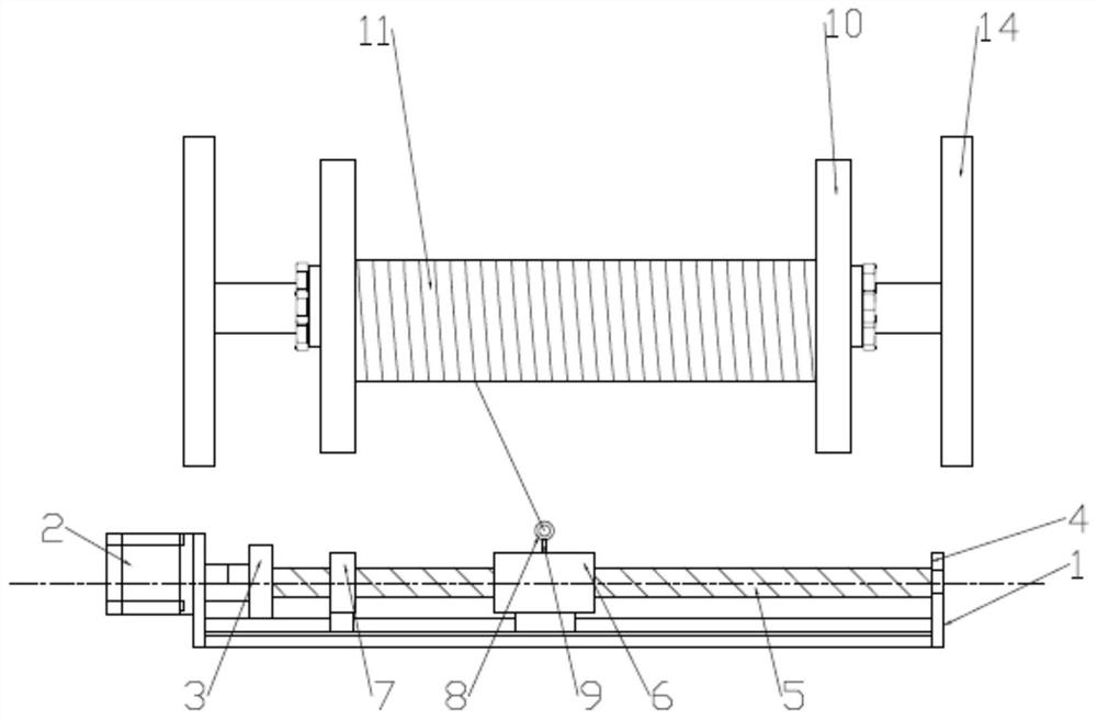
[0034] 1. The start-stop switch of the automatic cable arrangement device is connected in parallel with the start-stop of the take-up reel 11, so that the take-up reel 11 and the automatic cable arrangement device can be started and stopped at the same time;

[0035] 2. Collect the position of the sliding block 6 through the limit stop 7, and cont...

Embodiment 3

[0042] This embodiment is basically the same as the first embodiment, the difference is: figure 1 As shown, when arranging the wire, the traditional take-up reel 11 is prone to inversion after taking up the wire, thus seriously affecting the tightness of the take-up reel 11 when taking up the wire. Therefore, if the wire take-up reel 11 is reversed, the tightness of the cable will also be affected. Therefore, the present application also has a device for preventing the wire take-up reel 11 from being reversed.

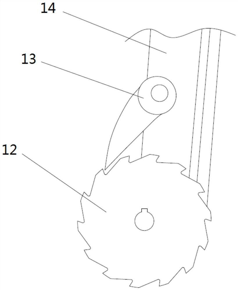
[0043] The take-up reel 11 is circular, and the take-up reel 11 is installed on the frame. The take-up reel 11 includes an inner take-up reel and an outer take-up reel, wherein the inner take-up reel rotates around the rotating shaft, and the outer take-up reel is arranged on the inner take-up reel. On the outside of the spool, a limit ratchet 12 is arranged on both sides of the outer take-up reel, and the limit ratchet 12 surrounds the outer take-up reel for a full ci...


PUM


Abstract

The invention discloses an automatic wire arranging device which comprises a support and a transverse moving device. Mounting seats are arranged on the bracket and comprise a first mounting seat and a second mounting seat; a first mounting hole is formed in the middle of the first mounting seat, a second mounting hole is formed in the middle of the second mounting seat, and a transverse moving device is mounted through the first mounting hole and the second mounting hole; the transverse moving device comprises a lead screw and a sliding block; the sliding block is installed on the lead screw, a wire passing device is arranged on the upper surface of the sliding block and comprises a wire passing ring, a connecting column and an installation plate, and the wire passing ring is used for supporting a steel wire rope. The automatic wire arranging device is arranged, when a steel wire rope is taken up, the steel wire rope is supported through a rope passing ring on the automatic wire arranging device, and the steel wire rope is driven to move left and right, so that the steel wire rope is uniformly arranged on the take-up reel, and the take-up process is rapid and stable; the production efficiency is improved, and the production cost is saved.

Description

technical field [0001] The invention belongs to wire rope winding equipment, in particular to an automatic wire arranging device. Background technique [0002] In the production process of steel wire rope, the steel wire needs to be manufactured into the steel wire of the required size and strength through a series of processes, so the use of the wire take-up device is essential. [0003] However, the existing wire take-up device technology for steel wire production lines has the following problems: At present, during the flexible wire-receiving process of wire ropes or cables, because the wire take-up device is directly connected to the wire-arranging device, the wire rope is directly removed after leaving the wire-paying device. The wire take-up device takes up the wire, which leads to disorderly arrangement of the wire take-up, uneven collection, and slippage after too much local winding, resulting in a jam in the wire take-up process, resulting in low production efficien...

Claims


Application Information

Patent Timeline
Patent Type & Authority Applications(China)
IPC IPC(8): B21C47/14
CPCB21C47/14
Inventor 张明吴永贵韩凯黄禹铭赵文秋
Owner 多普勒电梯股份有限公司
Why Eureka
Try Eureka