Sleeving and pasting jig for precise plastic part

A precision plastic and jig technology, applied in the field of consumer electronics processing, can solve problems such as inability to guarantee product cleanliness, product appearance damage, and difficulty in meeting mass production, and achieve improved fitting accuracy, production efficiency and good quality. efficiency and improve operational efficiency

Pending Publication Date: 2022-07-01
昆山摩建电子科技有限公司
View PDF0 Cites 0 Cited by
  • Summary
  • Abstract
  • Description
  • Claims
  • Application Information

AI Technical Summary

Problems solved by technology

At present, manual lamination is often used, but the appearance of the product will be damaged during production, and the cleanliness of the product cannot be guaranteed, and it is difficult to meet mass production

Method used


Image

  • Sleeving and pasting jig for precise plastic part
  • Sleeving and pasting jig for precise plastic part
  • Sleeving and pasting jig for precise plastic part

Examples


Embodiment 1

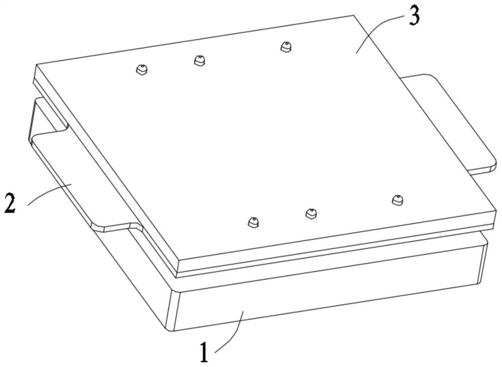
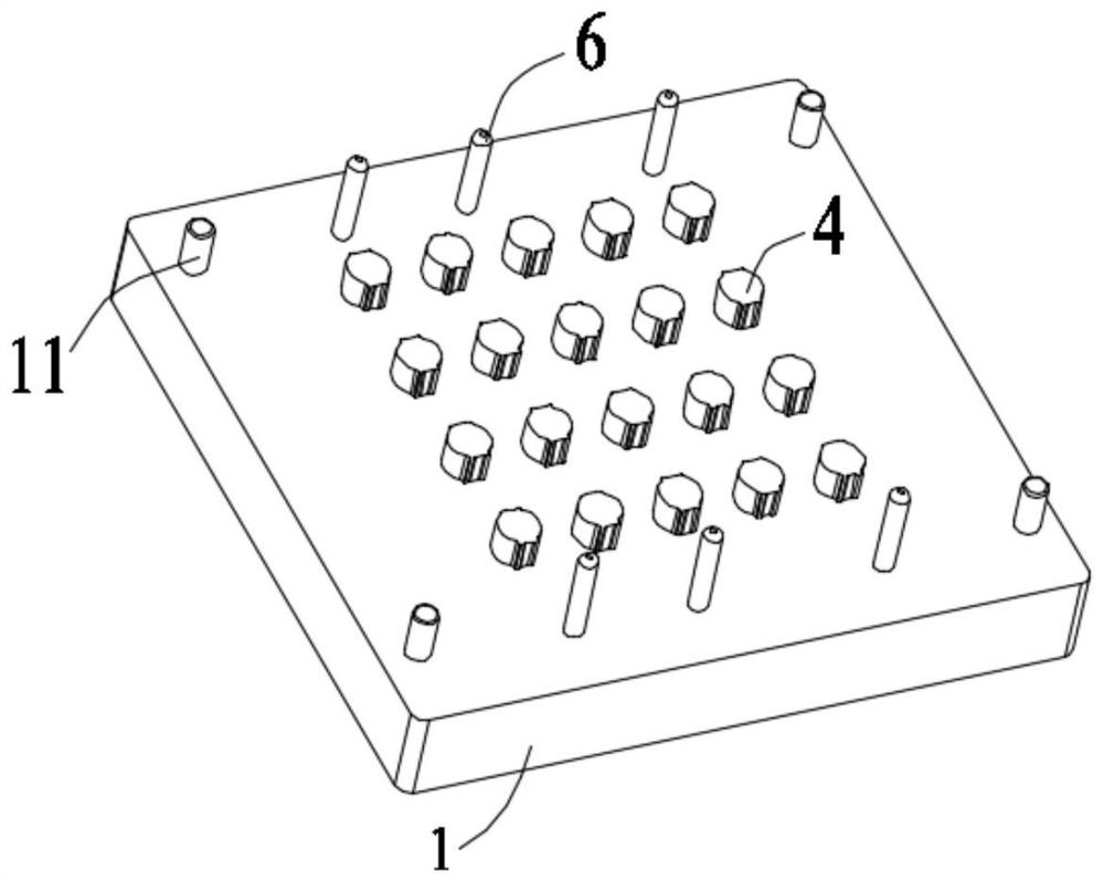
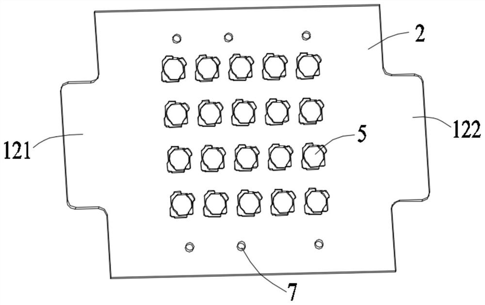
[0021] Embodiment 1: A sleeve jig for precision plastic parts, comprising: a base plate 1, a copy plate 2 and a cover plate 3, the copy plate 2 is located between the base plate 1 and the cover plate 3, the base plate 1 is provided with a number of bosses 4 at intervals, the profiling plate 2 is provided with a number of profiling grooves 5 corresponding to the bosses 4 for placing plastic parts, and the base plate 1 is located on a number of bosses 5. There are several positioning pins 6 on both sides of the table 4, and through holes 7 corresponding to the positioning pins 6 are opened on both sides of the several copying grooves 5 on the profile plate 2, and the surface of the boss 4 has a weak surface. The sticky double-sided adhesive layer 8, the surface of the weakly sticky double-sided adhesive layer 8 opposite to the boss 4 is attached with a foam layer 9, and the surface of this foam layer 9 is covered with a strong-stick double-sided adhesive layer 10;

[0022] The f...

Embodiment 2

[0027] Embodiment 2: A sleeve jig for precision plastic parts, comprising: a base plate 1, a copy plate 2 and a cover plate 3, the copy plate 2 is located between the base plate 1 and the cover plate 3, the base plate 1 is provided with a number of bosses 4 at intervals, the profiling plate 2 is provided with a number of profiling grooves 5 corresponding to the bosses 4 for placing plastic parts, and the base plate 1 is located on a number of bosses 5. There are several positioning pins 6 on both sides of the table 4, and through holes 7 corresponding to the positioning pins 6 are opened on both sides of the several copying grooves 5 on the profile plate 2, and the surface of the boss 4 has a weak surface. The sticky double-sided adhesive layer 8, the surface of the weakly sticky double-sided adhesive layer 8 opposite to the boss 4 is attached with a foam layer 9, and the surface of this foam layer 9 is covered with a strong-stick double-sided adhesive layer 10;

[0028] The f...


PUM


Abstract

The invention discloses a sleeve pasting jig for precise plastic parts, which comprises a base plate, a profiling plate and a cover plate, the profiling plate is located between the base plate and the cover plate, a plurality of bosses are arranged on the base plate at intervals, a plurality of profiling grooves corresponding to the bosses and used for placing the plastic parts are formed in the profiling plate, and the cover plate is located in the profiling grooves. The surface of the boss is provided with a weakly-sticky double-faced adhesive tape layer, a foam layer is adhered to the surface, opposite to the boss, of the weakly-sticky double-faced adhesive tape layer, and the surface of the foam layer is covered with a strongly-sticky double-faced adhesive tape layer; the four corners of the base plate are each provided with a spring pin used for supporting the profiling plate, and the height of the spring pins in the natural state is larger than that of the bosses; a left convex lug part and a right convex lug part are arranged on the left side and the right side of the profiling plate correspondingly. According to the sleeving and pasting jig for the precise plastic part, the plastic part can be conveniently placed in the profiling groove in the profiling plate, the production efficiency and the yield are greatly improved, and the pasting precision of the plastic part and a foam layer is also improved.

Description

technical field [0001] The invention relates to a sleeve sticking fixture for precision plastic parts, belonging to the technical field of consumer electronics processing. Background technique [0002] With the development of industrialization, more and more industries need to use precision plastic parts. With the increasing processing requirements, it is often necessary to paste foam double-sided tape and other materials on the precision plastic parts to protect them. . At present, manual lamination is often used, but the appearance of the product will be damaged during production, the cleanliness of the product cannot be guaranteed, and it is difficult to meet mass production. Therefore, how to improve the lamination efficiency and product yield of precision plastic parts and foam has become the direction of those skilled in the art. SUMMARY OF THE INVENTION [0003] The purpose of the present invention is to provide a jig for precision plastic parts, the jig for preci...

Claims


Application Information

Patent Timeline
Patent Type & Authority Applications(China)
IPC IPC(8): B29C65/78B29C65/48
CPCB29C65/7805B29C65/48
Inventor 张国干欧阳卓
Owner 昆山摩建电子科技有限公司
Why Eureka
Try Eureka