
Rear structure for vehicle

A rear structure and vehicle technology, which is applied to the lower structure, upper structure, vehicle components, etc., can solve the problems of small collision force and insufficient impact distribution on the right side member

Pending Publication Date: 2022-07-01
HYUNDAI MOTOR CO LTD +1
View PDF0 Cites 0 Cited by
  • Summary
  • Abstract
  • Description
  • Claims
  • Application Information

AI Technical Summary

Problems solved by technology

In addition, due to the broken rear beam of the vehicle, the impact distribution is not sufficient, so the impact force is absorbed by the right side member less

Method used


Image

  • Rear structure for vehicle
  • Rear structure for vehicle
  • Rear structure for vehicle

Examples


Embodiment approach

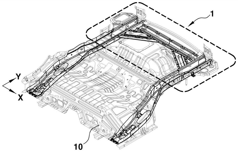
[0040]According to one embodiment of the present invention, the cross member 20 includes end flanges 22 configured to bend from both sides of the cross member 20 . The end flanges 22 are formed to be bent from both sides of the cross member 20 in the longitudinal direction of the cross member 20 . The end flange 22 is configured to have a contour corresponding to the rear floor 10 for attachment to the lower surface of the rear floor 10 .

[0041] The side extensions 30 are joined to both ends of the cross member 20, respectively. The side extensions 30 are joined to both sides of the lower surface of the rear floor panel 10 . The side extending portions 30 extend to a predetermined distance in the longitudinal direction (Y direction) of the vehicle along both side surfaces of the rear floor 10 .

[0042] The side extensions 30 are joined to the lower surface of the rear floor 10 to form a corresponding second space S2 together with the rear floor 10 , which is an empty spac...


PUM


Abstract

A rear structure for a vehicle includes a rear floor and a pair of inclined members joined to a lower surface of the rear floor and configured to be symmetrical to each other with respect to a longitudinal center line of the rear floor, each of a pair of tilt members extends from a first side and a second side of the rear floor, respectively, to a rear portion of the rear floor.

Description

technical field [0001] The present invention relates to a rear structure for a vehicle. Background technique [0002] The statements in this section merely provide background information related to the present invention and may not constitute prior art. [0003] A hybrid electric vehicle (HEV) is driven using an engine and a motor. The motor drives the HEV by receiving electric power stored in the battery and electric power through regenerative braking or the like, and when the electric power stored in the battery drops to a certain level, the engine drives the HEV. The HEV can be driven while driving by continuously charging the battery through self-generation and regenerative braking. Therefore, HEVs exhibit low fuel consumption and low pollutant emissions and are considered environmentally friendly vehicles. [0004] A plug-in hybrid electric vehicle (PHEV) is a type of HEV, and a larger capacity battery is installed as compared with a conventional HEV. The PHEV is dr...

Claims


Application Information

Patent Timeline
Patent Type & Authority Applications(China)
IPC IPC(8): B62D25/20B62D21/15
CPCB62D25/2027B62D21/152B62D25/087B62D21/15B62D27/02B60Y2306/01B60Y2410/124
Inventor 金成勋朴柱雄
Owner HYUNDAI MOTOR CO LTD
Learn More