Anti-biting optical cable
A technology of optical cable and optical fiber cavity, which is applied in the field of anti-bite optical cables, and can solve the problems of long service life of anti-bite optical cables, poor anti-bite performance, and lack of anti-bite performance of optical cables.
- Summary
- Abstract
- Description
- Claims
- Application Information
AI Technical Summary
Problems solved by technology
Method used
Image
Examples
Embodiment 1
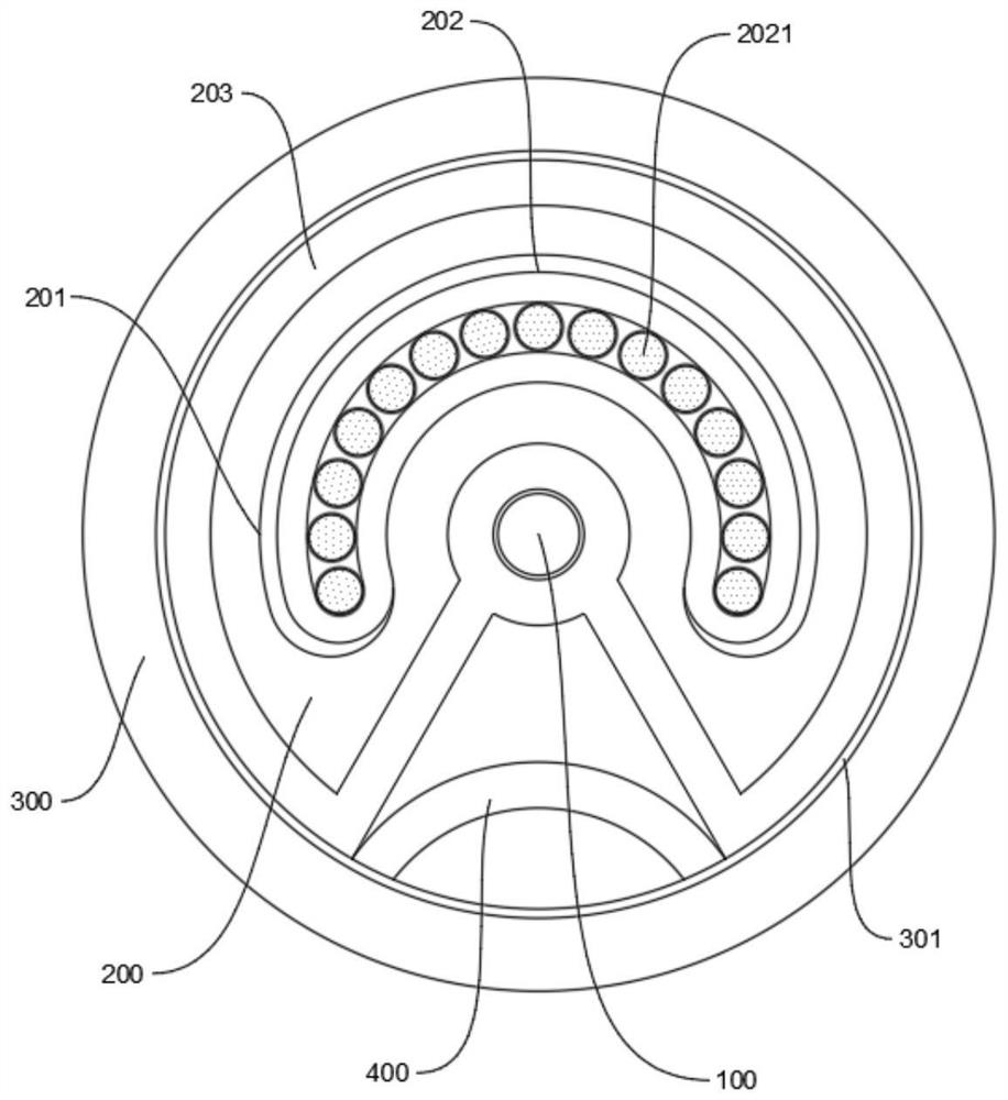
[0043] such as figure 1 Anti-bite fiber optic cable shown, which specifically includes:
[0044] The central reinforcement 100, the inner sheath 200 and the outer sheath 300 are sequentially arranged from the inside to the outside;
[0045] The inner sheath 200 is U-shaped, and is provided with an arc-shaped optical fiber cavity 201. The optical fiber cavity 201 is provided with a row-type optical fiber sleeve 202, and the row-type optical fiber sleeve 202 is provided with a number of optical fiber lines 2021. , the optical fiber line 2021 is a single optical fiber or an optical fiber bundle composed of multiple optical fibers;
[0046] The row-type optical fiber sleeve 202 is loosely installed in the optical fiber cavity 201;
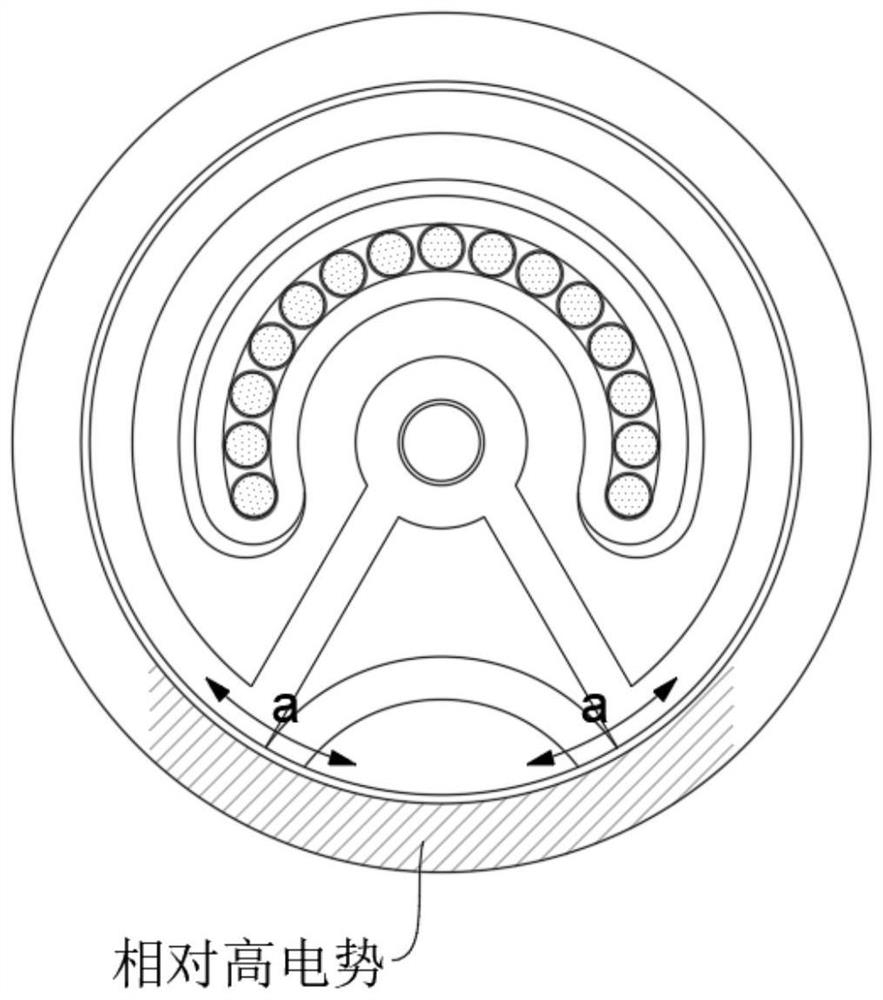
[0047] The outer surface of the inner sheath 200 is covered with an insulating armor layer 203 that isolates static electricity. The insulating armor layer 203 extends to the center of the optical cable and is covered on the outer surface of the cent...
Embodiment 2
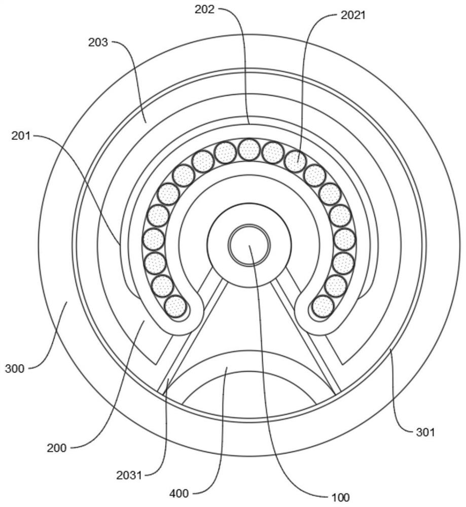
[0057] Due to the structural characteristics of the optical cable of the present invention, the optical cable of the present invention has an eccentric feature, and the center of gravity does not coincide with the cable core, and in the process of being bitten by rodents, the actual row of optical fiber sleeves 202 will meet the inner sheath 200. The optical fiber cavity 201 produces relative friction, and the way of loose fitting makes the relative friction more frequent;
[0058] Therefore, the row-type optical fiber ferrule 202 and the inner sheath 200 are further improved;
[0059] like image 3 As shown, the inner sheath 200 and the row-type optical fiber sleeve 202 are both made of polyurethane material, a conductive film 2031 is provided on the surface of the V-shaped opening of the insulating armor layer 203, and the row-type optical fiber sleeve 202 passes through the optical fiber cavity 201 , pass through the inner sheath 200 and part of the insulating armor layer ...
PUM
 Abstract
Description
Claims
Application Information
 - R&D
- Intellectual Property
- Life Sciences
- Materials
- Tech Scout
- Unparalleled Data Quality
- Higher Quality Content
- 60% Fewer Hallucinations
Browse by: Latest US Patents, China's latest patents, Technical Efficacy Thesaurus, Application Domain, Technology Topic, Popular Technical Reports.
© 2025 PatSnap. All rights reserved.Legal|Privacy policy|Modern Slavery Act Transparency Statement|Sitemap|About US| Contact US: help@patsnap.com


