
Spiral sand washer

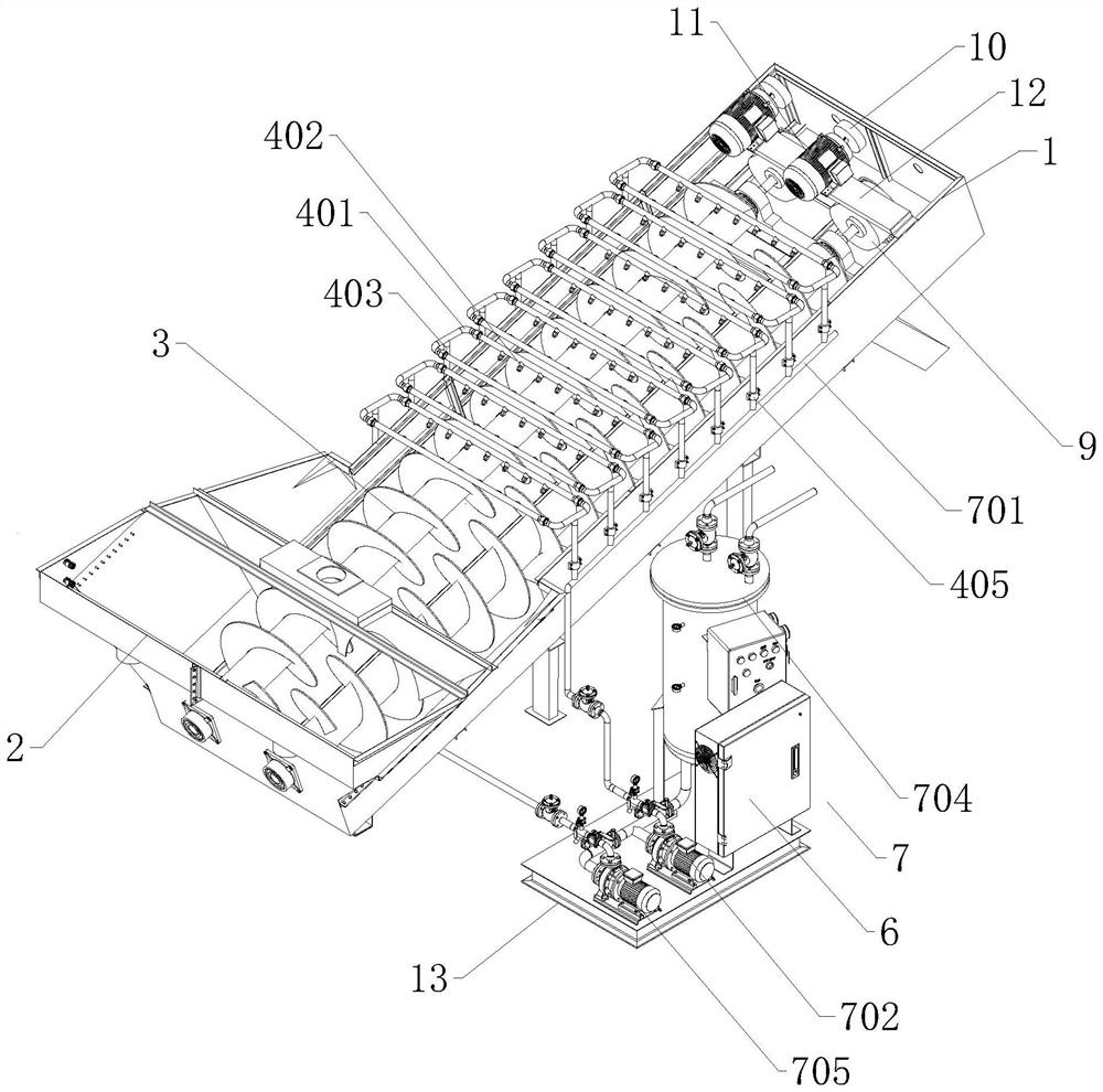
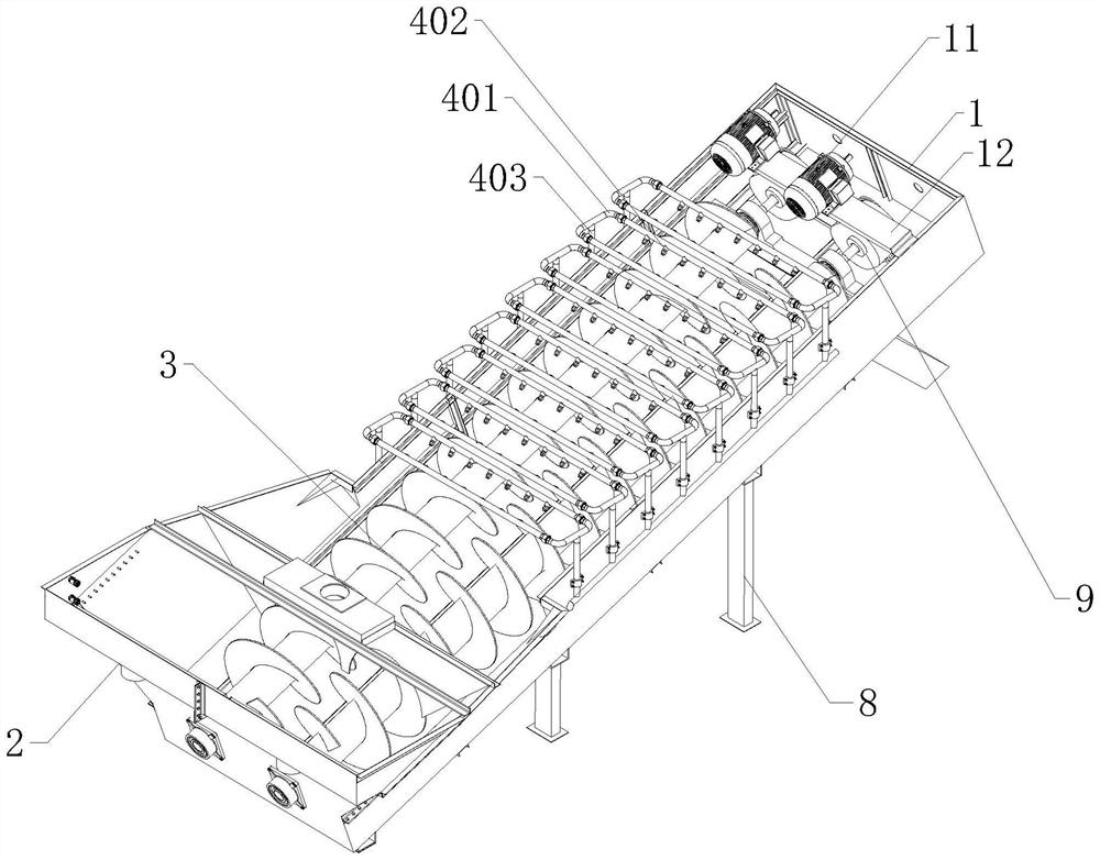
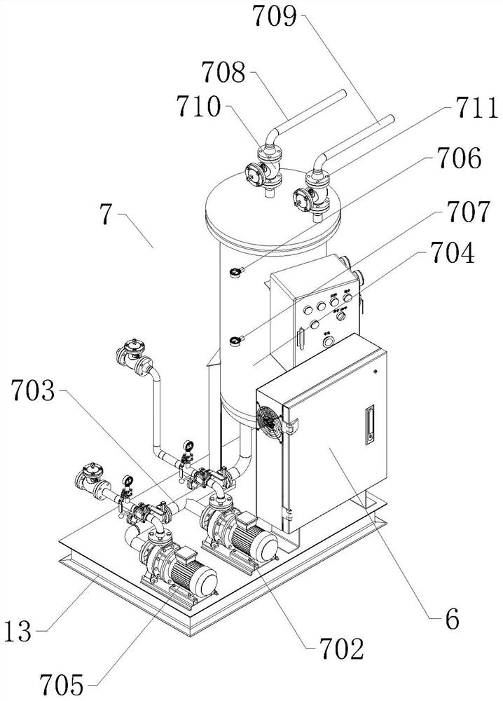
A technology of sand washing machine and spiral, applied in the field of sand washing machine, can solve the problems of working environment impact, the water volume of sedimentation tank can not be effectively controlled, water resource waste and so on

Pending Publication Date: 2022-07-05
JIANGSU SHANBAO GRP
View PDF0 Cites 0 Cited by
  • Summary
  • Abstract
  • Description
  • Claims
  • Application Information

AI Technical Summary

Problems solved by technology

[0002] The spiral sand washing machine is a kind of sand washing machine. It mainly stirs the sand and gravel through the spiral device in the equipment, so that the soil and water in the sand and gravel are mixed and discharged from the orifice on the equipment, while the sand and gravel are in the Under the action of the spiral device, it is gradually screened and discharged from the discharge port at the top, thus realizing the cleaning and screening effect of sand and gravel. The spiral sand washing machine has three functions of cleaning, dehydration and grading. When using the spiral sand washing machine, it needs to be tilted , the bottom of the tank of the spiral sand washing machine is equipped with a sedimentation tank composed of multiple groups of weir plates, and the water supply pipeline or the circulating clean water supply pipeline are connected to the water supply pipeline through the porous plate inside the sedimentation tank to inject cleaning water into the spiral sand washing machine, ensuring The normal operation of the spiral sand washing machine, but at present the sedimentation tank in the spiral sand washing machine is not equipped with a water level detection structure, resulting in the inability to effectively control the water volume of the sedimentation tank, resulting in water overflowing the sedimentation tank, resulting in waste of water resources, and at the same time It will affect the working environment, and the spiral blades of the current spiral sand washing machine will adhere to the soil during the cleaning process, which will reduce the cleaning efficiency when rotating the sand cleaning machine

Method used


Image

  • Spiral sand washer
  • Spiral sand washer
  • Spiral sand washer

Examples


Embodiment Construction

[0025] The technical solutions in the embodiments of the present invention will be described clearly and completely below in conjunction with the embodiments of the present invention. Obviously, the described embodiments are only a part of the embodiments of the present invention, rather than all the embodiments. Embodiments, and all other embodiments obtained by those of ordinary skill in the art without creative efforts, fall within the protection scope of the present invention.

[0026] In order to facilitate the understanding of the present invention, the present invention will be more fully described below with reference to the related drawings, and several embodiments of the present invention are given. However, the present invention can be implemented in many different forms, and is not limited to Examples, rather, these examples are provided so that this disclosure will be thorough and complete.

[0027] It should be noted that when an element is referred to as being "...


PUM


Abstract

The invention relates to the technical field of sand washers, in particular to a spiral sand washer which comprises a tank body, a sedimentation tank is arranged at the bottom of the tank body, and the opposite side walls in the tank body and the sedimentation tank are rotationally connected to spiral blades through bearings. A spiral blade cleaning assembly is correspondingly connected to the position, located on the side wall of the tank body, above each independent blade in the spiral blades, a liquid level detection assembly is arranged on the side wall of the sedimentation tank, and the liquid level detection assembly is electrically connected to the PLC control box through a wire; by means of the design, real-time monitoring of the water amount of the sedimentation tank is achieved, the problems that water overflows from the sedimentation tank, water resources are wasted, and the working environment is affected are solved, in the spiral blade cleaning process, the cleaning efficiency is improved, and the service life of the sedimentation tank is prolonged. And soil adhering to the surfaces of the spiral blades is cleaned, and the cleaning efficiency of the spiral sand washer is guaranteed.

Description

technical field [0001] The invention relates to the technical field of sand washing machines, in particular to a spiral sand washing machine. Background technique [0002] Spiral sand washing machine is a kind of sand washing machine. It mainly stirs the sand and gravel materials through the screw device in the equipment, so that the soil and water in the sand and gravel materials are mixed and discharged from the flow outlet on the equipment, while the sand and gravel materials are Under the action of the screw device, it is gradually screened and discharged from the discharge port at the top, so as to realize the cleaning and screening effect of the sand and gravel materials. The spiral sand washer has three functions of cleaning, dehydration and classification. , The bottom of the spiral sand washer tank is provided with a sedimentation tank composed of multiple groups of weir plates, and the water supply pipeline or circulating clean water supply pipeline is connected to...

Claims


Application Information

Patent Timeline
Patent Type & Authority Applications(China)
IPC IPC(8): B03B5/52B08B3/02B01D21/34B03B13/04
CPCB03B5/52B08B3/022B01D21/34B03B13/04
Inventor 王文峰
Owner JIANGSU SHANBAO GRP
Learn More