
Edge sweeping assembly and cleaning robot

A component and side sweeping technology, applied in the field of cleaning robots, can solve problems such as the breakage of the connecting bar 12 and the breakage of the single-tuft hair-planting brush body, and achieve the effects of high production efficiency, simple structure and high cleaning efficiency.

Inactive Publication Date: 2021-04-30
SHENZHEN SILVER STAR INTELLIGENT TECH CO LTD
View PDF6 Cites 0 Cited by
  • Summary
  • Abstract
  • Description
  • Claims
  • Application Information

AI Technical Summary

Problems solved by technology

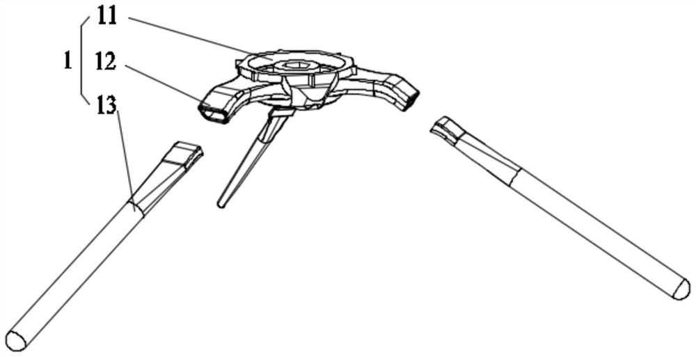
[0003] This structure tends to cause the single-tuft bristle-planting brush body 13 to break from the connection with the connection bar 12 or break in the middle of the connection bar 12 due to the reaction force of the ground or obstacles during the use of the cleaning robot.

Method used


Image

  • Edge sweeping assembly and cleaning robot
  • Edge sweeping assembly and cleaning robot
  • Edge sweeping assembly and cleaning robot

Examples


Embodiment 1

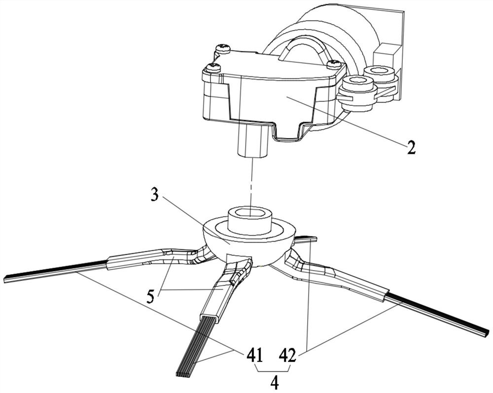
[0053] Such as figure 2 as shown, figure 2 It is a three-dimensional exploded view of the side sweep assembly and the drive assembly of the present invention. The side sweep assembly of the present invention can be connected with the drive assembly 2, as follows.

[0054] The drive assembly 2 can be a drive assembly 2 such as a motor that provides a rotating force, or a drive assembly 2 that provides a single-directional reciprocating force such as an air cylinder or a hydraulic cylinder, or a motor plus a transmission mechanism to provide a single-direction reciprocation Force drive assembly 2. The transmission mechanism is used to convert rotation into translation, such as a belt transmission mechanism.

[0055] The side sweep components include:

[0056] Body 3, the body 3 has a connection portion connected to the drive assembly 2, in this embodiment, the connection portion is a groove, the drive assembly 2 is a motor, the output end of the motor has a flat shaft porti...

Embodiment 2

[0087] Such as Figure 10 as shown, Figure 10 It is a structural schematic diagram of the cleaning robot of the present invention.

[0088] The present invention further provides a cleaning robot, including the side sweeping assembly described in the above embodiment, and the side sweeping assembly is arranged at the bottom of the cleaning robot.

[0089] Cleaning robots include:

[0090] Machine main body 6, machine main body 6 can be oval, circular, D-shaped and other shapes, and according to the needs, select settings for installing cleaning modules, walking modules, fan components, control components, distance sensing components, cliff sensors, water tanks and sewage Various parts such as boxes; the cleaning module can include side sweep components and middle sweep components;

[0091] The side sweep assembly, the side sweep assembly can be installed on the edge of the machine body 6 to clean the position that the middle sweep assembly cannot cover, and roll up the obj...


PUM


Abstract

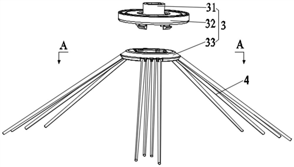
The invention relates to the field of cleaning equipment, in particular to a side sweeping assembly and a cleaning robot, the side sweeping assembly is provided with a body and at least one bristle cluster, all the bristle clusters are fixedly connected to the body, the body is provided with a connecting part connected with a driving assembly, and when the driving assembly drives the side sweeping assembly, the body acts to drive the bristle clusters with the two ends facing the to-be-cleaned face to act together, the two ends of each bristle cluster extend out from different angles with the body as the center and both face the to-be-cleaned face, and the two ends of each bristle cluster can extend out from the body at different angles with the body as the center. The connecting position of the bristle cluster and the body is changed from the end of the bristle cluster to the position between the two ends, so that the single bristle cluster is not prone to breakage from the connecting position of the bristle cluster and the body, and the two ends of the bristle cluster face the to-be-cleaned face and can be used for cleaning the to-be-cleaned face. By means of the structure, the problem that single-cluster planted hair is prone to breakage from the joint of the single-cluster planted hair and the connecting strip or breakage in the middle of the connecting strip is solved.

Description

technical field [0001] The invention relates to the field of cleaning equipment, in particular to a side sweeping assembly and a cleaning robot. Background technique [0002] The cleaning module of the cleaning robot usually includes a middle sweeping module and a side sweeping part 1. The middle sweeping module is a roller brush 7 assembly with a negative pressure port. When the cleaning robot cleans the surface to be cleaned, the roller brush 7 keeps rotating to remove dust, garbage Wait for the cleaning object to be rolled and sucked into the negative pressure port, so that the object to be cleaned enters the dust box connected with the negative pressure port. The side sweeper 1 plays a very important role as an auxiliary cleaning module that makes up for the inability to clean the edge of the cleaning robot. The existing side sweeper 1 usually includes a frame body 11 and a plurality of connecting bars 12 arranged horizontally around the frame body 11. A single cluster ...

Claims


Application Information

Patent Timeline
IPC IPC(8): A47L11/24A47L11/40
CPCA47L11/24A47L11/4038A47L11/4061A47L2201/00
Inventor 鲍呈祥
Owner SHENZHEN SILVER STAR INTELLIGENT TECH CO LTD
Learn More