Yarn tension adjusting device and spinning equipment

A technology for adjusting device and yarn tension, which is applied in the field of yarn tension adjusting device and textile equipment, which can solve problems such as adverse effects of yarn conveying stability, adverse effects of production, and yarn jumping, so as to prevent yarn breakage or jumping , Improve production efficiency and avoid breakage

Pending Publication Date: 2022-07-05
南通宏澳纺织有限公司
View PDF1 Cites 0 Cited by
  • Summary
  • Abstract
  • Description
  • Claims
  • Application Information

AI Technical Summary

Problems solved by technology

[0004] But there are still big deficiencies in the prior art, as: 1, when the tension regulator pulls the yarn to increase the tension adjustment, the pressure between the tension regulator and the yarn increases, and the frictional force also increases, making the yarn easy to adjust. It breaks due to factors such as pressure increase and temperature rise, which adversely affects production; 2. When the tension regulator pulls the yarn to adjust the tension, the yarn and the tension regulator are temporarily separated, and the yarn jumping phenomenon is prone to occur , which adversely affects the smoothness of yarn delivery, which in turn adversely affects production

Method used


Image

  • Yarn tension adjusting device and spinning equipment
  • Yarn tension adjusting device and spinning equipment
  • Yarn tension adjusting device and spinning equipment

Examples


Embodiment 1

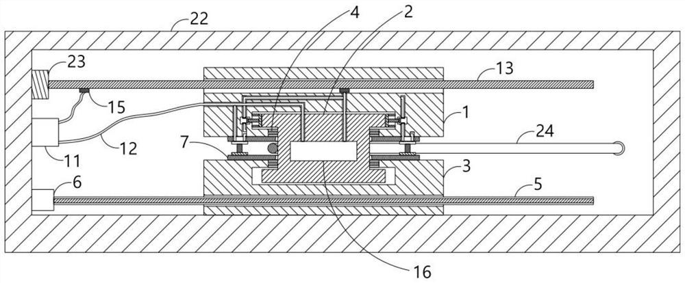
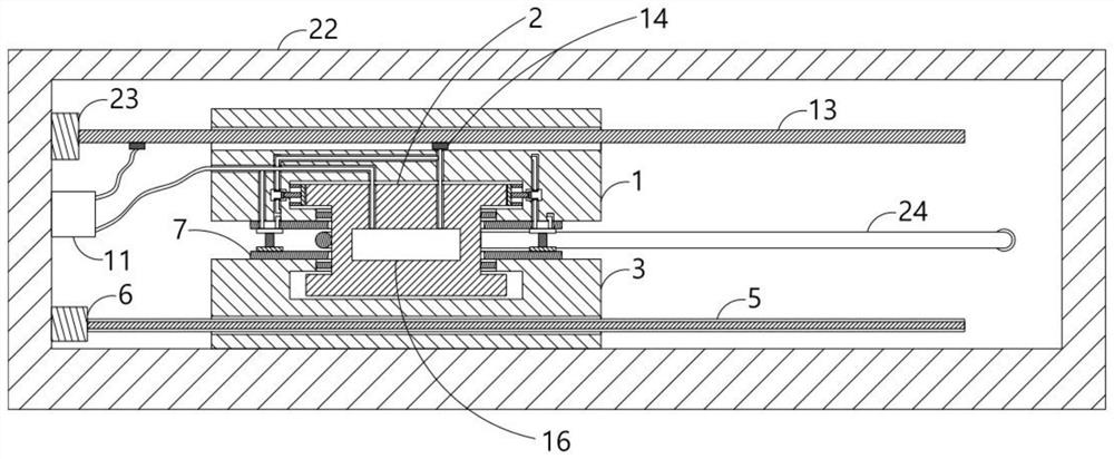
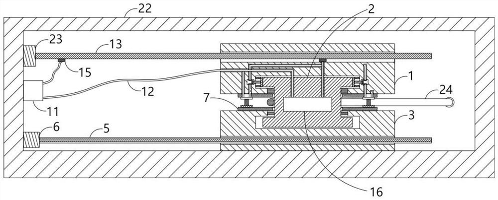
[0036] A yarn tension adjustment device includes an adjustment mechanism driven by an adjustment motor 6 to slide, the yarn 24 slides through the adjustment mechanism during the conveying process, and the adjustment motor 6 drives the adjustment mechanism to slide according to the tension of the yarn 24 during the conveying process. , so as to tighten or relax the yarn 24 to realize the adjustment of the tension of the yarn 24. The adjustment mechanism includes a first cover plate 1, an adjustment wheel 2, a second cover plate 3 and a control circuit. The adjustment wheel 2 is wide at both ends and a middle part. Narrow I-shaped structure, the adjustment wheel 2 of the I-shaped structure is convenient for both ends of the adjustment wheel 2 to extend into the first cover plate 1 and the second cover plate 3, and the two ends of the adjustment wheel 2 are respectively movable into the first cover plate. 1. In the second cover plate 3, the yarn 24 slides through the adjustment wh...

Embodiment 2

[0045] The second embodiment provides a way of adjusting the motor 6 to drive the adjusting mechanism to slide on the basis of the first embodiment, that is: the tension signal receiver is installed in the adjusting motor 6, and the tension signal receiver receives the tension of the yarn 24 in real time, and according to The difference between the actual tension of the yarn 24 and the suitable tension drives the adjustment motor 6 to work, and the output end of the adjustment motor 6 is installed with a threaded screw 5, and the second cover plate 3 is provided with an inner thread that cooperates with the threaded screw 5. The threaded groove, the adjusting motor 6 drives the threaded screw 5 to rotate, and drives the second cover 3 to slide through the threaded transmission between the threaded screw 5 and the second cover 3, and the second cover 3 slides to drive the adjustment wheel 2 to slide together. The wheel 2 slides to adjust the tension of the yarn 24. The thread dr...

Embodiment 3

[0047] The third embodiment discloses the specific structure of the trigger switch on the basis of the first embodiment, that is, the trigger switch includes a push plate 17 and a push rod 19 fixedly connected to one end of the push plate 17 away from the adjustment wheel 2, and the push plate 17 is connected to the first end of the push plate 17. An elastic connecting rod 18 is fixedly connected between the inner walls of the cover plate 1 , a power receiving rod 20 is fixedly connected to the end of the push rod 19 away from the push plate 17 , and the wire 12 is electrically connected with two power connecting rods that are electrically connected to the power receiving rod 20 . Plate 21, the first cover plate 1 is provided with a trigger switch cavity 101, the push rod 19 slides into the trigger switch cavity 101, the power receiving rod 20 and the two power receiving plates 21 are located in the trigger switch cavity 101, and the two power The plates 21 are arranged at inte...


PUM


Abstract

The invention discloses a yarn tension adjusting device and textile equipment, elastic connecting blocks are fixedly connected between an adjusting wheel and a first cover plate and between the adjusting wheel and a second cover plate, the outer side of the adjusting wheel is movably sleeved with two pressing plates, and electromagnets and magnetic plates which are magnetically attracted are fixedly arranged on the end faces of the two pressing plates correspondingly; an elastic supporting column is fixedly connected between the electromagnet and the magnetic plate, the control circuit comprises a power source, a resistance rod and a refrigerator which are electrically connected through a wire, the refrigerator is connected with a trigger circuit in parallel, the trigger circuit comprises two trigger switches which are arranged in parallel, and the adjusting wheel is located between the two trigger switches. Through cooperative arrangement of a resistance rod, a fixed power connection block and a sliding power connection block, the refrigerating capacity of the refrigerator is adjusted, and through cooperative arrangement of a trigger switch and an electromagnet, in the sliding process of the adjusting wheel, the problem that yarn is broken or jumps is solved.

Description

technical field [0001] The invention relates to the technical field of textile equipment, in particular to a yarn tension adjustment device and textile equipment. Background technique [0002] In the process of yarn spinning, the control of yarn tension is particularly important. The level of yarn tension control directly determines the grade and quality of the produced products. Most of the existing tension adjusters are equipped with a spring adjustment mechanism. The spring in the spring adjustment mechanism is easy to be damaged and difficult to inspect. Once the elasticity of the spring changes, the tension adjuster cannot adjust the tension of the yarn normally, resulting in winding. The wire equipment cannot be wound evenly, resulting in the inability of the entire process to proceed normally. [0003] In the prior art, a yarn tension adjusting device with publication number "CN210103073U" includes a tension frame and a tension regulator. The tension frame is provide...

Claims


Application Information

Patent Timeline
Patent Type & Authority Applications(China)
IPC IPC(8): B65H59/10B65H63/02B65H63/04F25B49/00
CPCB65H59/10B65H63/02B65H63/04F25B49/00
Inventor 施建
Owner 南通宏澳纺织有限公司
Why Eureka
Try Eureka