Stem cell extraction system

An extraction system and stem cell technology, applied in the field of stem cell extraction system, can solve problems such as poor continuous operation

Pending Publication Date: 2022-07-05
陶军
View PDF0 Cites 0 Cited by
  • Summary
  • Abstract
  • Description
  • Claims
  • Application Information

AI Technical Summary

Problems solved by technology

[0003] However, the system used in each step is a separate system, which is not easy to operate continuously, and the extraction effect needs to be further improved

Method used


Image

  • Stem cell extraction system
  • Stem cell extraction system
  • Stem cell extraction system

Examples


Embodiment 1

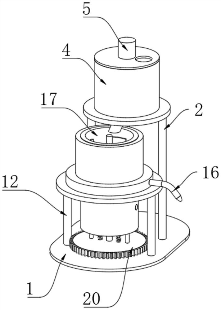
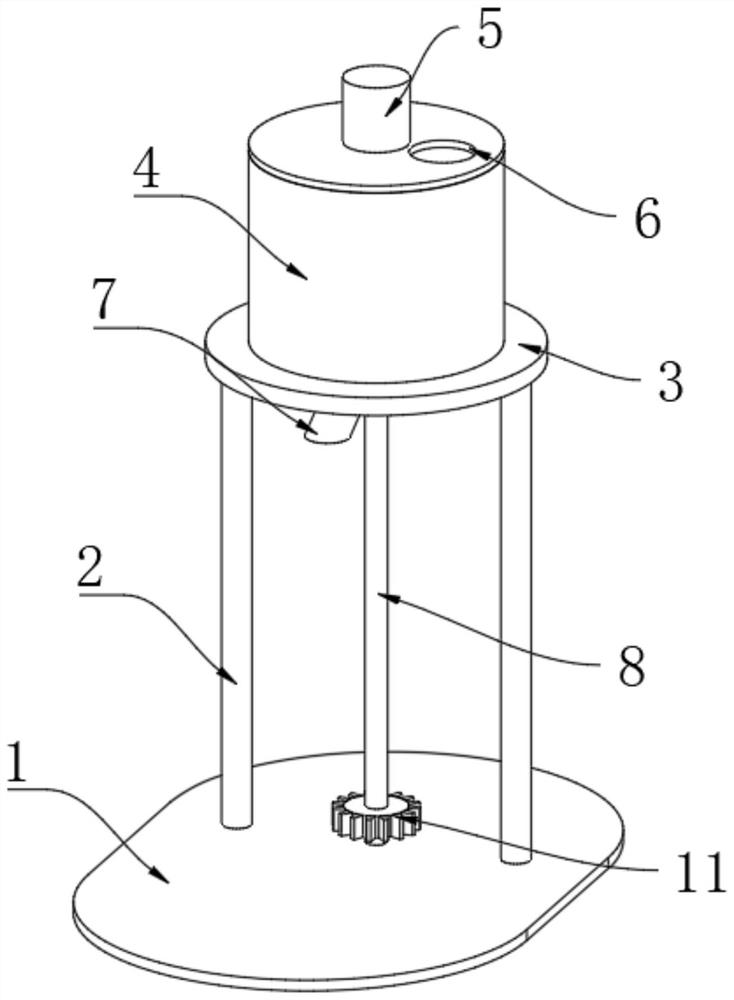
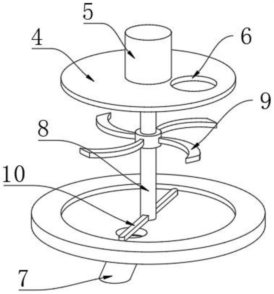
[0031] like Figure 1-Figure 3 As shown, a stem cell extraction system includes an installation base plate 1, the upper surface of the installation base plate 1 is fixedly connected with a support column 1 2, the top of the support column 1 2 is fixedly connected with an installation collar 1 3, and the inner wall of the installation collar 1 is fixed A pulverizing box 4 is connected, and a driving motor 5 is fixedly installed in the middle of the upper surface of the pulverizing box 4. The output end of the driving motor 5 extends to the interior of the pulverizing box 4 and is fixedly connected with a rotating shaft 8, and the bottom end of the rotating shaft 8 penetrates Gear one 11 is fixedly connected to the lower surface of the crushing box 4 and the bottom end of the rotating shaft 8, the bottom of the gear one 11 is fixedly connected to the upper surface of the mounting base plate 1 for rotation, and the outer wall of the rotating shaft 8 is fixedly connected to the int...

Embodiment 2

[0047] like Figure 10 As shown, on the basis of the first embodiment, the scraper 30 is replaced with a brush plate 36. The specific replacement scheme is: the inner wall of the digestion tank 17 is fixedly connected with the support plate 28 relative to the upper position of the cylinder 26, and the connecting rod 21 Running through the upper surface of the support plate 28, the outer wall of the connecting rod 21 is fixedly connected with four groups of evenly distributed stirring rods 29 relative to the upper position of the support plate 28. Closed brush plate 36.

[0048] Since the brush plate 36 is always in contact with the inner wall of the digestion tank 17, when the digestion tank 17 rotates, the brush plate 36 will scrape off the sticky solution on the inner wall of the digestion tank 17, which is beneficial to the subsequent cleaning work. The plate 36 will continuously scrape the position of the liquid outlet 18 with the liquid outlet 18 to prevent the liquid ou...


PUM


Abstract

The invention discloses a stem cell extraction system which comprises a mounting bottom plate, a first supporting column is fixedly connected to the upper surface of the mounting bottom plate, a first mounting lantern ring is fixedly connected to the top end of the first supporting column, and a crushing box is fixedly connected to the inner wall of the first mounting lantern ring; a driving motor is fixedly mounted in the middle of the upper surface of the crushing box body, the output end of the driving motor extends into the crushing box body and is fixedly connected with a rotating shaft, the bottom end of the rotating shaft penetrates through the lower surface of the crushing box body, and the bottom end of the rotating shaft is fixedly connected with a gear I. A certain amount of collagenase is added into an inner cavity of the digestion tank; the driving motor is started, the cleaned placentas are poured into the inner cavity of the smashing box body from the position of the feeding opening, the rotating shaft is driven by the driving motor to rotate, then the smashing blades are driven to rotate, the placentas in the inner cavity of the smashing box body are rapidly smashed, and the placentas can conveniently react with collagenase in the follow-up process.

Description

technical field [0001] The invention relates to the technical field of stem cell extraction, in particular to a stem cell extraction system. Background technique [0002] The function of stem cell population is to control and maintain cell regeneration. At present, the extraction of placental stem cells has entered a new stage of research. Usually, the extraction of stem cells from the placenta is washed with phosphate buffer, etc., the clean placenta is cut into pieces and then immersed in an enzyme solution for digestion, and then the digested solution is sampled. [0003] However, the system used in each step is a separate system, which is not suitable for continuous operation, and the extraction effect needs to be further improved. SUMMARY OF THE INVENTION [0004] The purpose of the present invention is to provide a stem cell extraction system, which has the advantages of continuously crushing the placenta, good digestion treatment effect, automatic sampling, and goo...

Claims


Application Information

Patent Timeline
Patent Type & Authority Applications(China)
IPC IPC(8): C12M1/40C12M1/33C12M1/02C12M1/10C12M1/26C12M1/00
CPCC12M21/18C12M45/02C12M27/16C12M27/10C12M27/02C12M39/00C12M33/00
Inventor 不公告发明人
Owner 陶军
Why Eureka
Try Eureka