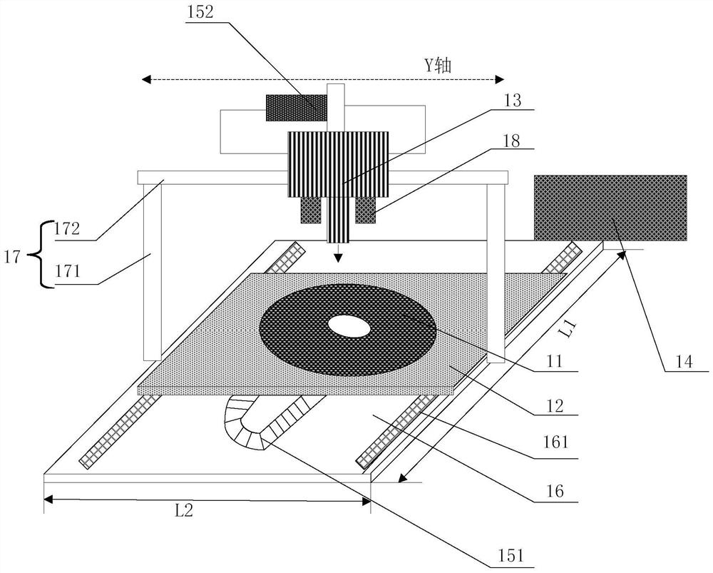
Polishing pad hole pricking equipment and polishing pad hole pricking method

A polishing pad and equipment technology, applied in the field of silicon wafer manufacturing, can solve the problems of easily broken needles, large needle tip torque, and difficulty in inspection, etc., to avoid needle breakage, improve surface flatness, and improve polishing yield.

Pending Publication Date: 2022-07-08
ZING SEMICON CORP
View PDF0 Cites 0 Cited by
  • Summary
  • Abstract
  • Description
  • Claims
  • Application Information

AI Technical Summary

Problems solved by technology

[0005] In view of the shortcomings of the prior art described above, the object of the present invention is to provide a polishing pad piercing device and a polishing pad piercing method, which are used to solve the problem of using a roller-type needle roller tool with multiple needles mounted on the surface in the prior art. For manual rolling of the polishing pad, it is difficult to achieve the same installation height among the needles, and it is difficult to achieve the same position, interval and depth of the needle hole due to manual operation, resulting in polishing The flatness of the pad surface is poor; and multiple needles on the needle rolling tool are rolled at the same time for piercing operation. During the rolling process, the needle tip is subjected to a large torque, which is prone to broken needles. The broken needles fall on the polishing pad and are not easy to detect. The product will be scratched in the middle, and there will be a large gap in the position of the broken needle during rolling, and the pinhole cannot be pierced. When the polishing pad is attached to the fixed plate, the air bubbles cannot be effectively removed, resulting in poor flatness of the polished product, etc.

Method used


Image

  • Polishing pad hole pricking equipment and polishing pad hole pricking method

Examples


Embodiment Construction

[0031] The embodiments of the present invention are described below by specific embodiments, and those skilled in the art can easily understand other advantages and effects of the present invention from the contents disclosed in this specification.

[0032] It should be noted that the structures, proportions, sizes, etc. shown in the drawings in this specification are only used to cooperate with the contents disclosed in the specification, so as to be understood and read by those who are familiar with the technology, and are not used to limit the implementation of the present invention. Restricted conditions, it does not have technical substantive significance, any structural modification, proportional relationship change or size adjustment, without affecting the effect that the present invention can produce and the purpose that can be achieved, should still fall within the present invention. The disclosed technical content must be within the scope of coverage. At the same tim...


PUM


Abstract

The invention provides polishing pad hole pricking equipment and a hole pricking method. The polishing pad pricking equipment comprises a bearing table, a pricking device and a driving device. The bearing table is used for placing a polishing pad to be punctured; the hole pricking device is located above the bearing table, and the hole pricking device comprises pricking needles and is used for conducting hole pricking operation on the polishing pad; the driving device is connected with the bearing table and / or the hole pricking device and used for driving the bearing table and / or the hole pricking device to move in the horizontal direction so as to conduct hole pricking operation on the preset position of the polishing pad. The control device is connected with the hole pricking device and the driving device so as to control operation of the hole pricking device and the driving device. According to the improved structural design, the control device controls the hole pricking device to conduct automatic hole pricking operation on the polishing pad, the consistency of the hole pricking position, interval and depth can be ensured, the surface flatness of the polishing pad is effectively improved, the problem of needle breakage caused by improper force during manual needle pricking can be effectively solved, and the production efficiency is improved. And the subsequent polishing yield can be improved.

Description

technical field [0001] The invention relates to the field of silicon wafer manufacturing, in particular to a polishing pad drilling equipment and a polishing pad drilling method. Background technique [0002] The polishing process is an important process in the silicon wafer manufacturing process. The step of improving the surface flatness of the silicon wafer by polishing determines the final morphology of the silicon wafer surface, which has a very important impact on the subsequent semiconductor device manufacturing yield. Therefore, various parameters in the polishing process, such as the flatness of the polishing pad , polishing head rotation speed, etc. must be strictly managed. [0003] In the double-sided polishing process of silicon wafers, polishing pads are attached to the upper and lower platens, the polishing liquid is poured into the upper platen, and the silicon wafers are placed on the planetary wheel. For the purpose of polishing, the surface flatness of t...

Claims


Application Information

Patent Timeline
Patent Type & Authority Applications(China)
IPC IPC(8): B24D11/00
CPCB24D11/008Y02P70/50
Inventor 刘福成何昆哲华千慧
Owner ZING SEMICON CORP
Why Eureka
Try Eureka