Check patentability & draft patents in minutes with Patsnap Eureka AI!

Batch hoisting load analysis method for steel members

An analysis method and technology for steel components, applied in the field of hoisting analysis, can solve problems such as low calculation efficiency, and achieve the effects of saving labor costs, improving analysis efficiency, and improving accuracy

Pending Publication Date: 2022-07-08
CHINA CONSTR SCI & IND CORP LTD
View PDF0 Cites 0 Cited by
  • Summary
  • Abstract
  • Description
  • Claims
  • Application Information

AI Technical Summary

Problems solved by technology

[0003] Therefore, the technical problem to be solved by the present invention is to overcome the defect of low efficiency in hoisting analysis and calculation of large-span space grids in the prior art, so as to provide an efficient method for batch hoisting analysis of steel components

Method used


Image

  • Batch hoisting load analysis method for steel members
  • Batch hoisting load analysis method for steel members
  • Batch hoisting load analysis method for steel members

Examples


Embodiment 1

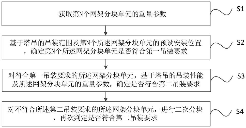
[0041] combine Figure 1-Figure 6 As shown, the method for analyzing the batch hoisting weight of steel components provided in this embodiment includes:

[0042] S1. Obtain the weight parameter of the N-th grid block unit. Among them, N is a positive integer.

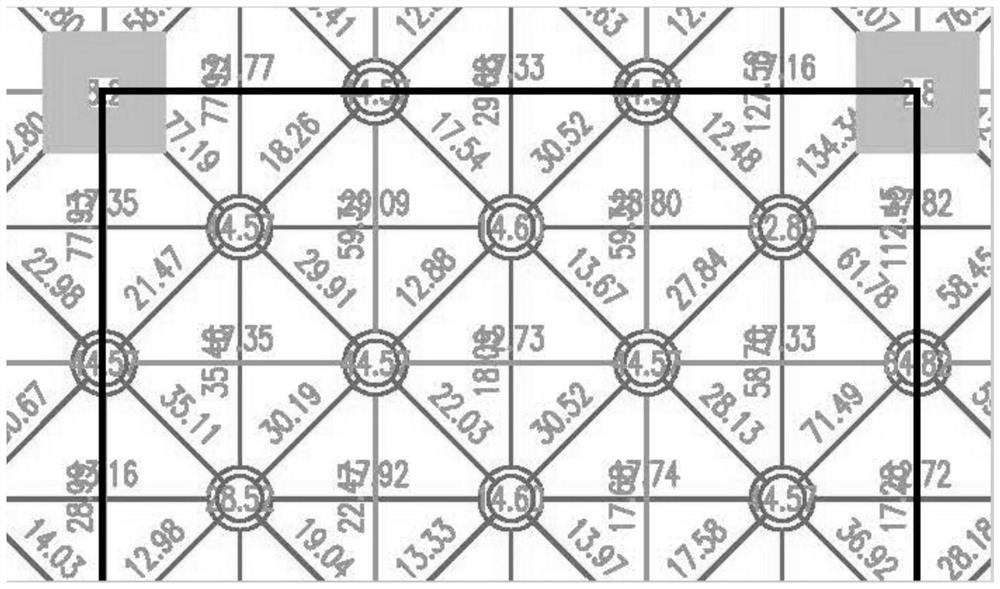
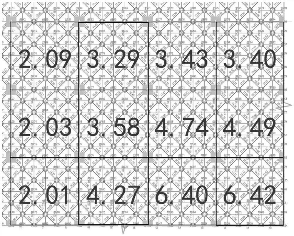
[0043] Preferably, in order to complete the assembly of a space grid, it is necessary to first divide the space grid into N grid block units; Figure 4 As shown in the figure, due to the limitation of the hoisting range of the tower crane, and at the same time, each tower crane has the limitation of the hoisting capacity according to its own parameters, therefore, in the hoisting process of the grid block unit, it is necessary to carry out N grid block units one by one. Analysis, according to the predetermined installation position of each grid block unit, determine whether it is within the hoisting range of the tower crane, and according to the weight of each grid block unit, determine whether it is within the range ...

Embodiment 2

[0077] The present embodiment provides a batch hoisting weight analysis device for steel components, including:

[0078] The acquisition module is used to acquire the weight parameter of the Nth grid block unit;

[0079] The judgment module is used to determine whether the N-th grid frame sub-unit meets the first hoisting requirement based on the hoisting range of the tower crane and the preset installation position of the N-th grid frame sub-unit; The required grid block unit is determined based on the hoisting performance of the tower crane and the weight parameters of the grid block unit to determine whether it meets the second hoisting requirement; for the grid unit that does not meet the second hoisting requirement The block unit is divided into two blocks, and it is judged again whether it meets the second hoisting requirements; wherein, N is a positive integer.

[0080] This embodiment also provides an electronic device, comprising: a processor and a memory, where the ...


PUM


Abstract

The invention relates to the technical field of hoisting analysis, in particular to a steel member batch hoisting weight analysis method. According to the steel member batch hoisting analysis method provided by the invention, the weight parameter of the Nth net rack block unit is obtained, and whether the Nth net rack block unit meets the first hoisting requirement or not is determined based on the hoisting range of the tower crane and the preset mounting position of the Nth net rack block unit; further, on the basis of the hoisting performance of the tower crane and the weight parameters of the net rack partitioning units, whether the net rack partitioning units meet the second hoisting requirement or not is determined, secondary partitioning is conducted on the net rack partitioning units which do not meet the second hoisting requirement, and whether the net rack partitioning units meet the second hoisting requirement or not is judged again; therefore, the block size problem of the net rack and the hoisting equipment selection problem can be quickly determined, the analysis efficiency is improved, the accuracy is improved, a large amount of time does not need to be spent, the labor cost is saved, and manual repeated accounting is not needed.

Description

technical field [0001] The invention relates to the technical field of hoisting analysis, in particular to a method for analyzing batch hoisting weight of steel components. Background technique [0002] The large-span space grid is a space structure formed by connecting multiple rods through nodes according to a certain grid form. It is widely used in workshops, coal sheds in power plants and other scenarios. Because the large-span space grid usually needs to be hoisted after being divided into blocks, in the prior art, in the face of the analysis of the hoisting method of the large-span space complex hyperbolic grid, the main problem to be solved is the block size of the grid. problems and the selection of hoisting equipment, traditional solutions to these two problems require a lot of manual repetitive calculations. Not only does it take a lot of time, but the accuracy is difficult to guarantee. SUMMARY OF THE INVENTION [0003] Therefore, the technical problem to be s...

Claims


Application Information

Patent Timeline
Patent Type & Authority Applications(China)
IPC IPC(8): G06F30/13G06F30/20
CPCG06F30/13G06F30/20Y02P90/30
Inventor 程泽豪黄晓康魏大江崔旭爽李帅李志永高占文郝雪冬
Owner CHINA CONSTR SCI & IND CORP LTD
Features
  • R&D
  • Intellectual Property
  • Life Sciences
  • Materials
  • Tech Scout
  • Unparalleled Data Quality
  • Higher Quality Content
  • 60% Fewer Hallucinations
Learn More