Supercharge Your Innovation With Domain-Expert AI Agents!

Circular saw blade and method for manufacturing circular saw blade

A circular saw blade and disc-shaped technology, which is applied in the manufacturing field of circular saw blades and circular saw blades, can solve problems such as intermittent frequency deviation

Pending Publication Date: 2022-07-08
KANEFUSA HAMONO KOUGIYOU KK
View PDF0 Cites 0 Cited by
  • Summary
  • Abstract
  • Description
  • Claims
  • Application Information

AI Technical Summary

Problems solved by technology

Therefore, each intermittent frequency corresponding to each cutting bit varies.

Method used


Image

  • Circular saw blade and method for manufacturing circular saw blade
  • Circular saw blade and method for manufacturing circular saw blade
  • Circular saw blade and method for manufacturing circular saw blade

Examples


Embodiment Construction

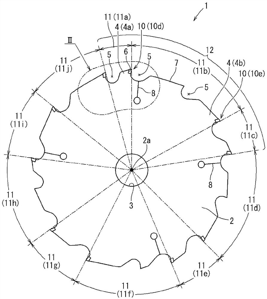
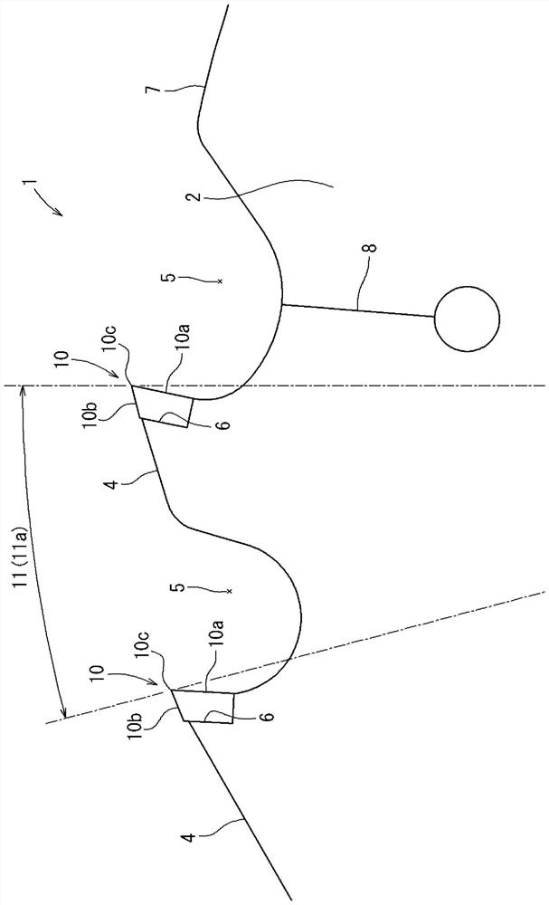
[0043] based on Figures 1 to 21 , the first embodiment of the present disclosure will be described. likefigure 1 As shown, the circular saw blade 1 has a disk-shaped base body 2 and a plurality of cutting tips 10 joined to the outer periphery of the base body 2 . The circular saw blade 1 is not a structure in which a plurality of base bodies 2 are joined, for example, but is used as a single body at the time of cutting. The circular saw blade 1 is rotatably attached to a cutting tool such as a rechargeable battery-type electric circular saw or a stationary circular saw blade cutter, for example. With regard to the circular saw blade 1, the base body 2 is rotated to form grooves in the workpiece with the respective cutting tips 10, and finally the workpiece is cut. The workpiece to be cut is, for example, wood, wood materials, resin materials, composite materials, or ceramic materials such as wall panels. Or the workpiece to be cut is carbon steel, rolled steel for general ...


PUM


Abstract

The circular saw blade (1) is used during cutting. A circular saw blade (1) is provided with a disc-shaped base body (2) and a plurality of cutting bits (10) joined to the outer periphery of the base body (2). The pitches (11) of the plurality of cutting bits (10) are configured from a plurality of different sizes. The ratio of the maximum pitch (11b) to the minimum pitch (11a) is at least three times.

Description

technical field [0001] One aspect of the present disclosure relates to a circular saw blade and a method of manufacturing the circular saw blade. Circular saw blades cut workpieces, such as wood and wood materials, ceramic materials such as outer walls, steel materials such as pipes, or non-ferrous metal materials such as aluminum. Background technique [0002] The circular saw blade has a disk-shaped base body and a plurality of cutting tips joined to the outer periphery of the base body. The cutting insert is composed of, for example, a cemented carbide or a polycrystalline diamond (PCD) sintered body. The cutting inserts are arranged at predetermined intervals (pitch) in the circumferential direction of the base body. The cutting tip is engaged with the base body in a posture in which the rake face faces the base body in the circumferential direction. By rotating the circular saw blade around an axis passing through the disk-shaped center of the base body, the cutting ...

Claims


Application Information

Patent Timeline
IPC IPC(8): B23D61/02B27B33/08B28D1/04B23D47/00
CPCB23D47/00B27B33/08B28D1/04B23D61/02
Inventor 浅香庆一渡部友朗
Owner KANEFUSA HAMONO KOUGIYOU KK
Features
  • R&D
  • Intellectual Property
  • Life Sciences
  • Materials
  • Tech Scout
  • Unparalleled Data Quality
  • Higher Quality Content
  • 60% Fewer Hallucinations
Learn More