
Electrically actuatable drive unit

A driving unit and electric operation technology, applied in the direction of electric components, brakes, electromechanical devices, etc., can solve problems such as inaccuracy, brake pressure adjustment influence, error, etc.

Pending Publication Date: 2022-07-08
ROBERT BOSCH GMBH
View PDF1 Cites 0 Cited by
  • Summary
  • Abstract
  • Description
  • Claims
  • Application Information

AI Technical Summary

Problems solved by technology

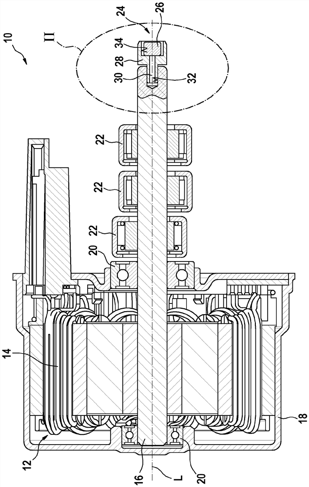
These relative movements lead to inaccuracies in the detection of the traversed angle of rotation of the motor shaft 16 and thus to a possibility in the electrical control of the electric motor 12 of the drive unit 10 or in the adjustment of the displaced pressure medium quantity. error
Ultimately has an undesired influence on the brake pressure regulation performed

Method used


Image

  • Electrically actuatable drive unit
  • Electrically actuatable drive unit
  • Electrically actuatable drive unit

Examples


Embodiment Construction

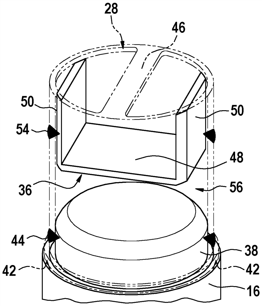
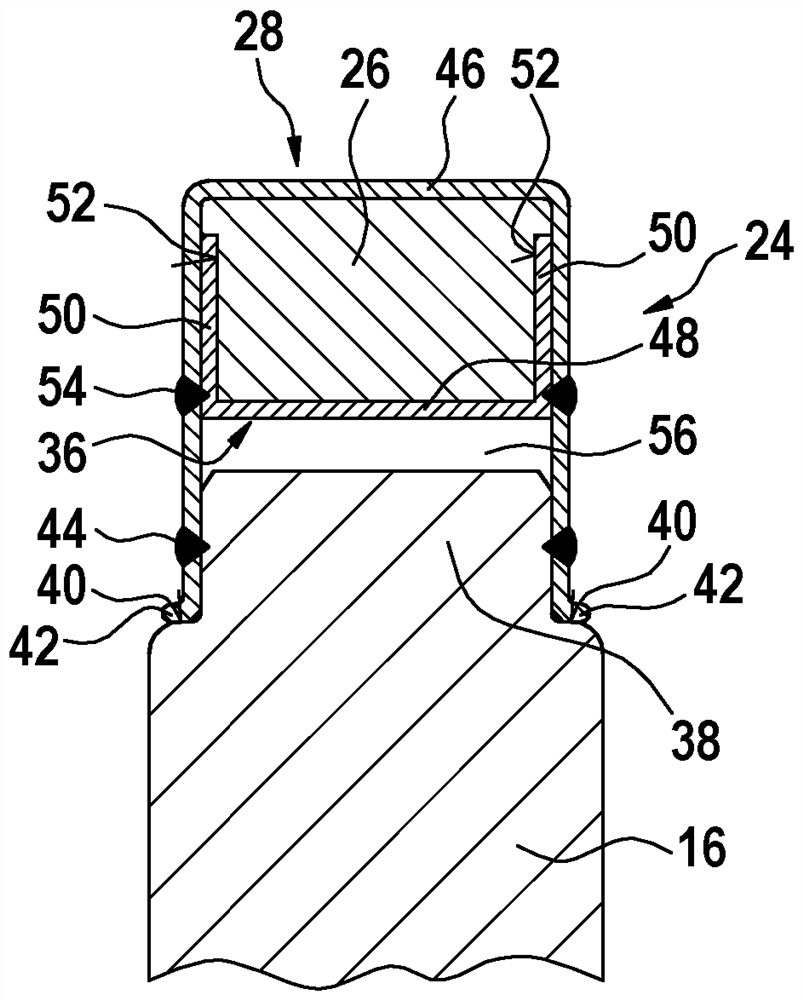
[0021] figure 2 According to the design according to the invention, according to figure 1 Details of X. The motor shaft 16 of the drive assembly 10 is shown in the region of the end of the motor shaft facing away from the rotor 14 of the electric motor 12 (not shown). according to figure 2 , this end of the motor shaft 16 is equipped with a signal transmitter 24 of the sensor device.

[0022] The signal transmitter 24 includes, as is known, a magnetic element 26 which is fastened on the front side of the motor shaft 16 by means of a holding element 28 made of a magnetically non-conductive material. According to the invention, the holding element 28 is produced as a hollow cylinder, within which the magnetic element 26 is accommodated and fixedly anchored by means of a clip element 36 . The hollow cylinder has an open first end with which it is pushed onto a shoulder 38 which is displaced in its outer diameter relative to the outer diameter of the motor shaft 16 . The tr...


PUM


Abstract

The invention relates to an electrically actuatable drive assembly (10) consisting of an electric motor (12) having a rotor (14) that can be driven for a rotational movement, a motor shaft (16) that is connected in a rotationally fixed manner to the rotor (14), and a signal transmitter (24) of a sensor device for electronically detecting and evaluating a rotational angle of the motor shaft (16). The signal transmitter (24) is indirectly anchored to the motor shaft (16) by means of a retaining element (28). The invention relates to a retaining element (28) which is produced as a hollow cylinder having an open first end, by means of which the retaining element (28) is fastened to the motor shaft (16) and which has a second end facing away from the motor shaft (16), by means of which the retaining element (28) is fastened to the motor shaft (16). The second end has at least one retaining element region (46) which protrudes into the open cross-section of the retaining element (28).

Description

technical field [0001] The invention relates to an electrically actuable drive unit according to the features of the preamble of claim 1 . Background technique [0002] Such drive units are used, for example, in electronically slip-adjustable braking systems of motor vehicles to drive pressure generators within the range of brake pressure regulation. The electrical actuation of the drive unit is carried out by the electronic control unit of the braking system. In the case of an electrical actuation of the drive unit, the thus actuated pressure generator delivers the pressure medium within the brake circuit from the storage container of the brake system to the connected wheel brakes. A brake pressure is then built up in the wheel brakes in proportion to the quantity of pressure medium supplied. [0003] By means of an additional control device which can be actuated by the electronic control unit, this brake pressure can be adapted in a wheel-individual manner to the slip ra...

Claims


Application Information

Patent Timeline
IPC IPC(8): H02K11/215
CPCH02K11/215B60T13/662B60T17/02B60T13/74B60T8/404H02K7/003H02K11/21
Inventor E·辛诺
Owner ROBERT BOSCH GMBH
Learn More