
Multi-stage accelerated rotational flow cavitation device

An acceleration tube and acceleration section technology, which is applied in transportation and packaging, chemical instruments and methods, chemical/physical processes, etc., can solve problems such as channel blockage, impurity accumulation, and oil and water well production reduction, so as to improve flow velocity, formation and No pollution to the environment and high energy conversion efficiency

Inactive Publication Date: 2022-07-12
SOUTHWEST PETROLEUM UNIV
View PDF5 Cites 3 Cited by
  • Summary
  • Abstract
  • Description
  • Claims
  • Application Information

AI Technical Summary

Problems solved by technology

[0003] During the long-term oilfield production work, many impurities will accumulate, drilling fluid and some salt substances will be deposited, which will lead to channel blockage and reduced production of oil and water wells

Method used


Image

  • Multi-stage accelerated rotational flow cavitation device
  • Multi-stage accelerated rotational flow cavitation device
  • Multi-stage accelerated rotational flow cavitation device

Examples


Embodiment Construction

[0027] The present invention will be further described below with reference to the specific embodiments and the accompanying drawings. The examples are only used to explain the present invention, and are not intended to limit the scope of the present invention.

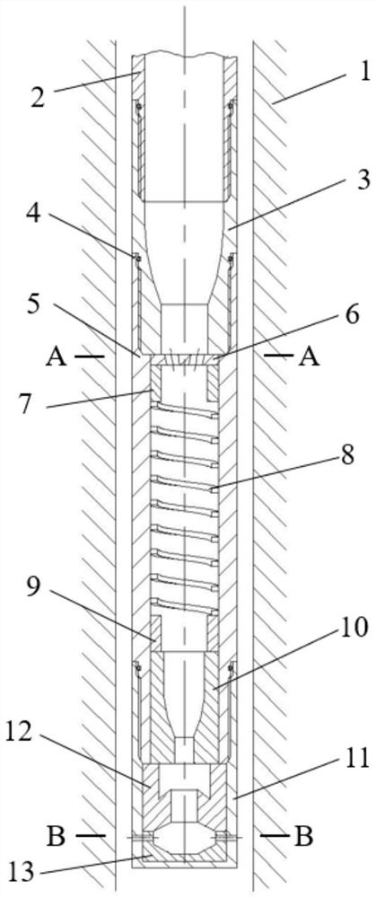
[0028] like figure 1 As shown, a multi-stage accelerated swirl cavitation device includes a first-stage shrinking tube 3, an accelerating tube 5, a mixed flow plate 6, a swirl acceleration section 8, a second-stage shrinking tube 10, a nozzle tube 11, and a self-vibrating cavitation cavity. 12. Conductive body 13;

[0029] The first-stage shrinking tube 3 is located above the accelerating tube 5, the two are connected by threads, and an O-ring is installed at the root of the thread;

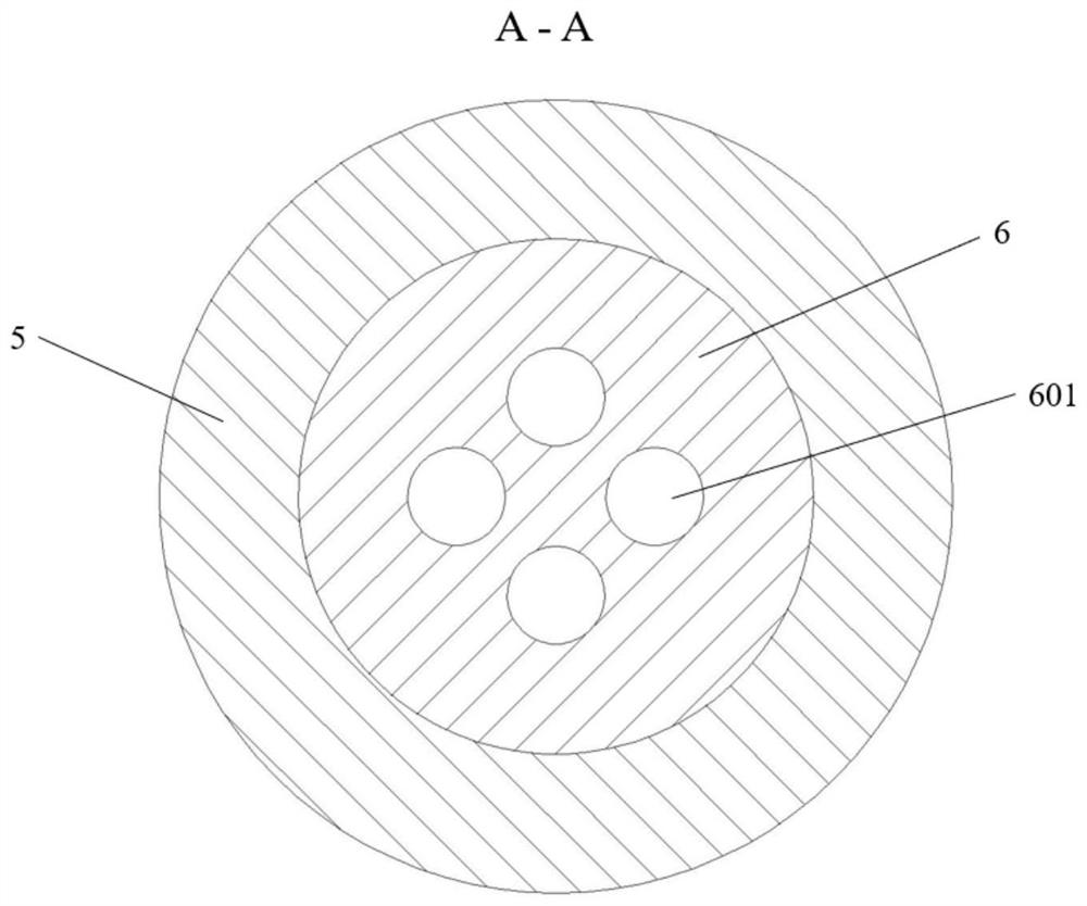
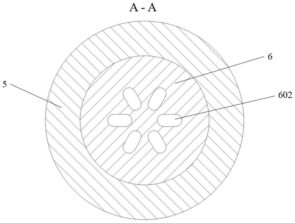
[0030] like figure 2 As shown, the mixed flow plate 6 is installed at the uppermost end of the acceleration tube 5, and the mixed flow plate 6 is provided with inclined through holes, the through holes are circular through holes 601, ...


PUM


Abstract

The invention relates to a multi-stage acceleration rotational flow cavitation device which comprises a first-stage shrinkage pipe, an acceleration pipe, a flow mixing plate, a rotational flow acceleration section, a second-stage shrinkage pipe, a nozzle pipe, a natural vibration cavitation cavity and a flow guide body, and the first-stage shrinkage pipe is located above the acceleration pipe and is in threaded connection with the acceleration pipe; the flow mixing plate is mounted at the uppermost end in the accelerating tube, and an inclined through hole is formed in the flow mixing plate; the rotational flow acceleration section is positioned below the flow mixing plate; the second-stage shrinkage pipe is located below the rotational flow acceleration section, and the diameter of each section of the second-stage shrinkage pipe is smaller than that of the first-stage shrinkage pipe; the nozzle pipe is located below the accelerating pipe, and a converging and flushing nozzle is arranged on the nozzle pipe; the flow guide body is installed at the bottom end of the nozzle pipe, and a through hole matched with the confluence flushing nozzle is formed in the flow guide body in the circumferential direction. The device is simple in structure and high in efficiency, the number of cavitation bubbles is increased through mutual impact of fluid, gas-liquid separation is generated through the rotational flow acceleration section, generation of cavitation bubbles is promoted again, different cavitation strengths are generated through the confluence nozzle, and oil and gas well blockage removal is better facilitated.

Description

technical field [0001] The invention belongs to the technical field of hydraulic cavitation, and in particular relates to a multi-stage accelerated swirl cavitation device, which is particularly suitable for unblocking oil and gas wells. Background technique [0002] Hydraulic cavitation refers to the fact that when the liquid and the solid move at a relatively high speed, when the liquid passes through the area where the cross section becomes smaller, the speed of the liquid increases, and the local pressure in the liquid decreases. When the pressure decreases to the saturated vapor pressure of the liquid, cavitation occurs continuously The process of formation, development and collapse. The collapse of the cavitation bubble will be accompanied by the generation of huge energy. Therefore, while cavitation is considered to be a "scourge", the hidden "potential" has also been discovered. It has been more than a hundred years since the discovery of cavitation. , people are co...

Claims


Application Information

Patent Timeline
Patent Type & Authority Applications(China)
IPC IPC(8): B01F33/82B01F23/20
Inventor 苟如意龙顺军康晨晨张金发蒋预祝胡沐峰邓潘朱文清
Owner SOUTHWEST PETROLEUM UNIV
Learn More