Automobile anti-collision beam mounting structure and mounting method

A technology of installation structure and installation method, which is applied to bumpers, combustion engines, internal combustion piston engines, etc., can solve the problem of reducing the energy absorption effect of the anti-collision beam body, pulling off the anti-collision beam at the connection, and weakening the strength of the anti-collision beam 1. and other problems, to achieve the effect of avoiding the collision force transmission path, enhancing the strength, and improving the impact resistance of the car body

Pending Publication Date: 2022-07-12
SHANGHAI LINGYUN IND TECH CO LTD
View PDF0 Cites 0 Cited by
  • Summary
  • Abstract
  • Description
  • Claims
  • Application Information

AI Technical Summary

Problems solved by technology

[0003] as attached figure 1 , figure 2 As shown, in the prior art, the automobile anti-collision beam 1 and the car body longitudinal beam 3 are connected by bolts 2, and the assembly structure is as follows: the bolt 2 passes through the bolt passing hole 1-1 on the outer arc surface of the cavity of the anti-collision beam 1, The inner arc surface of the anti-collision beam 1 cavity is directly screwed to the end of the longitudinal beam 3 of the vehicle body. This installation structure needs to consider the operating space of the bolt 2 and the tightening wrench tool. The size of the bolt hole is relatively large, which greatly weakens the strength of the anti-collision beam 1 here; in addition, the bolt 2 is connected by self-tapping thread, which can easily cause the joint to tear when the car body collides at high speed. As a result, the anti-collision beam will be pulled off prematurely at the joint, directly changing the transmission path of the collision force, reducing the energy absorption effect of the anti-collision beam body, and causing unpredictable damage to the car body

Method used


Image

  • Automobile anti-collision beam mounting structure and mounting method
  • Automobile anti-collision beam mounting structure and mounting method
  • Automobile anti-collision beam mounting structure and mounting method

Examples


Embodiment Construction

[0029] The present invention will be further described below with reference to the accompanying drawings and specific embodiments.

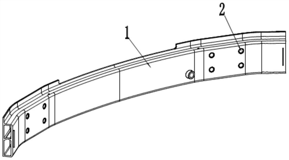
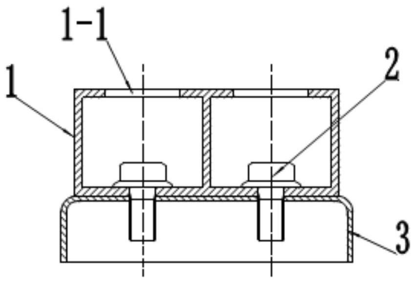
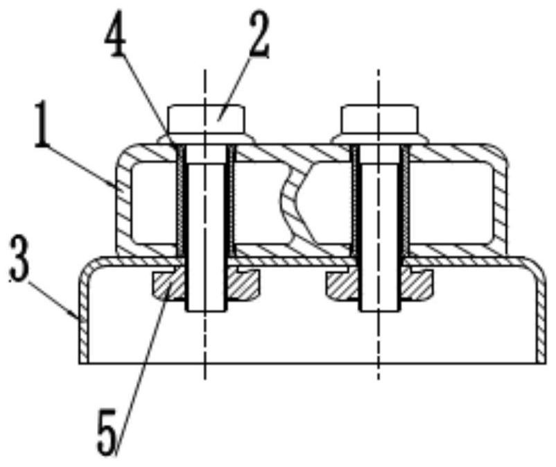
[0030] Referring to Figure 1, figure 2 , the anti-collision beam 1 of the car is a component of a cavity structure installed at the front end of the car body. When a frontal collision of the car body occurs, the impact energy can be absorbed by the collapse deformation of the anti-collision beam to reduce the damage to the car body. , in the prior art, the anti-collision beam 1 of the automobile and the body longitudinal beam 3 are connected and assembled by bolts 2, and the assembly structure is as follows: the bolts 2 pass through the holes 1-1 on the outer arc surface of the anti-collision beam 1 cavity. , directly screw the inner arc surface of the cavity 1 of the anti-collision beam with the end of the longitudinal beam 3 of the vehicle body. This installation structure needs to consider the operating space of the bolt 2 and the tightening ...


PUM


Abstract

The invention discloses an automobile anti-collision beam mounting structure and a mounting method. The automobile anti-collision beam mounting structure comprises an anti-collision beam, an automobile body longitudinal beam, a bolt, a reinforcing sleeve and a welding nut, the anti-collision beam is an arc-shaped cross beam matched with the outline shape of the front end of a vehicle body, the cross section of the anti-collision beam is of a hollow cavity structure, the two ends of the anti-collision beam are fixedly assembled with the front end face of a vehicle body longitudinal beam through bolts, and reinforcing sleeve assembly holes are formed in the inner side arc face and the outer side arc face of the matched position of the anti-collision beam and the front end face of the vehicle body longitudinal beam. A welding nut is pre-welded on the inner side wall of the front end surface of the vehicle body longitudinal beam; the two ends of the reinforcing sleeve are embedded in reinforcing sleeve assembly holes formed in the inner side arc face and the outer side arc face of the anti-collision beam respectively. The bolt penetrates through the reinforcing sleeve to be assembled with the welding nut. The strength of the joint of the anti-collision beam and the longitudinal beam of the automobile is effectively enhanced, the problem that a collision force transmission path is changed due to the fact that the anti-collision beam is pulled out too early at the joint is solved, and the purposes of improving the impact resistance of an automobile body and guaranteeing the safety of the automobile are achieved.

Description

technical field [0001] The invention relates to an automobile anti-collision beam, in particular to an installation structure and an installation method of the automobile anti-collision beam. Background technique [0002] With the rapid development of the automobile manufacturing industry, people have higher and higher requirements for the safety performance of automobiles. As an important safety component of the vehicle, the anti-collision beam can effectively absorb the collision energy and reduce the damage to the vehicle body when the vehicle body collides, so as to ensure the personal safety of the passengers. [0003] as attached figure 1 , figure 2 As shown, in the prior art, the automobile anti-collision beam 1 and the vehicle body longitudinal beam 3 are connected by bolts 2, and the assembly structure is as follows: the bolts 2 pass through the bolt holes 1-1 on the outer arc surface of the cavity of the anti-collision beam 1, The inner arc surface of the cavit...

Claims


Application Information

Patent Timeline
Patent Type & Authority Applications(China)
IPC IPC(8): B60R19/24B60R19/02
CPCB60R19/24B60R19/02Y02T10/40
Inventor 韩佳孙后青李欣葛磊尚建花
Owner SHANGHAI LINGYUN IND TECH CO LTD
Why Eureka
Try Eureka