Propeller structure and rapid developing and shaping method

A propeller and structure technology, which is applied in the field of propeller structure and rapid development and shaping, can solve the problem of pitch positioning operation not being able to adjust the propeller, and achieve the effect of saving mold opening cost and mold opening time, convenient and rapid operation and low cost.

Pending Publication Date: 2022-07-12
NANCHANG SANRUI INTELLIGENT TECH CO LTD
View PDF0 Cites 0 Cited by
  • Summary
  • Abstract
  • Description
  • Claims
  • Application Information

AI Technical Summary

Problems solved by technology

The operation of locating the corresponding pitch can only be carried out in the factory or indoor conditional operating desk, and the pitch positioning operation cannot be performed in the field, let alone the adjustment of the propeller already installed on the aircraft

Method used


Image

  • Propeller structure and rapid developing and shaping method
  • Propeller structure and rapid developing and shaping method
  • Propeller structure and rapid developing and shaping method

Examples


Embodiment 1

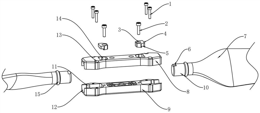
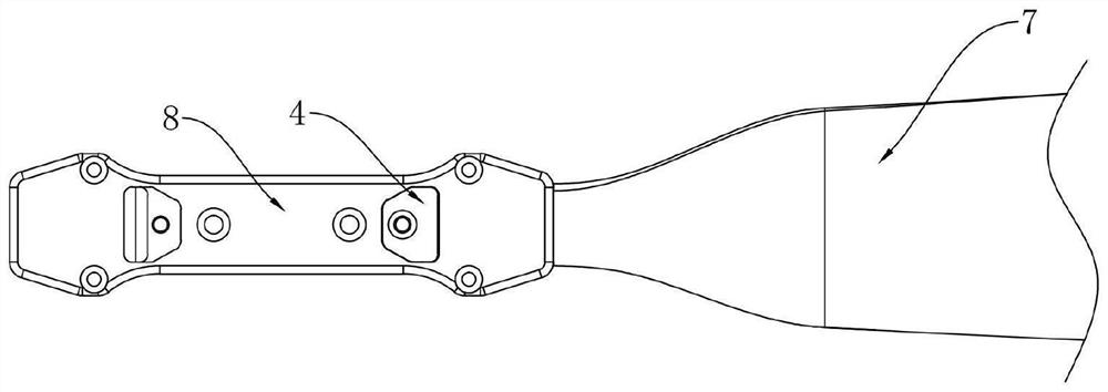
[0038] A specific embodiment of the present invention is shown in the accompanying drawings, a propeller structure includes a blade 7 and a propeller clip; also includes a plurality of positioning blocks 4 with mating surfaces 5 with different inclination angles;

[0039] Both sides of the paddle clip are provided with accommodating holes for accommodating the paddle 7 , and the paddle clip is provided with a positioning hole 14 for installing the positioning block 4 , and the positioning hole 14 communicates with the accommodating hole , the positioning block 4 is detachably arranged in the positioning hole 14;

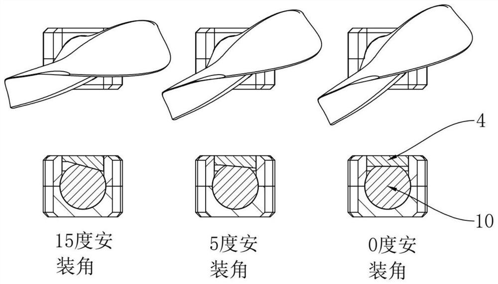
[0040] A positioning shaft 10 is provided at one end of the paddle clip that is matched with the accommodating hole, and a positioning shaft 10 is provided on the positioning shaft 10 to cooperate with the mating surface 5 of the positioning block 4 to realize the radial positioning of the positioning shaft (restrict the rotation of the positioning shaft). Limit surf...

Embodiment 2

[0046] A method for developing and shaping a propeller structure, the method comprises the following steps

[0047] 1. In the initial manufacturing stage of the project, prepare at least 2 to 3 sets of blade plans and make samples (several plans are the preferred main plans, using different local airfoils, chord length distribution, and blade tip designs), each The solutions all integrate the same positioning shaft structure at the root in advance, and make several sets of propeller clips with different installation lengths and several sets of positioning blocks with different angles. Propeller clips with different lengths are assembled with the same blade, and the maximum diameter of the blade can be adjusted, which can quickly realize the scheme verification of different blade lengths in a short period of time. The positioning blocks of different angles can quickly realize the installation and positioning of the blades with different pitches. Both can adjust the correspondi...


PUM


Abstract

The invention discloses a propeller structure and a rapid developing and shaping method. The propeller structure comprises propeller blades and propeller clamps. The positioning blocks are provided with matching surfaces with different inclination angles; accommodating holes for accommodating the paddles are formed in the two sides of the paddle clamp, positioning holes for mounting the positioning blocks are formed in the paddle clamp, the positioning holes are communicated with the accommodating holes, and the positioning blocks are detachably arranged in the positioning holes; a positioning rotating shaft is arranged at the end, matched with the containing hole, of the paddle clamp, and a limiting face matched with the matching face of the positioning block so as to achieve radial positioning of the positioning rotating shaft is arranged on the positioning rotating shaft. The screw pitch positioning and fastening work can be directly operated in an external field, and a special large-scale positioning tool is not needed; the performance test can be quickly carried out under different screw pitches and working conditions by opening a pair of molds to manufacture a pair of samples and then adjusting the screw pitches.

Description

technical field [0001] The invention relates to the technical field of aircraft, in particular to a propeller structure and a rapid development and shaping method. Background technique [0002] The existing one-piece carbon fiber propeller development process is that for each blade designed, the corresponding design scheme must be drawn out of the mold and then processed into a sample. In the early stages of development this process consumes considerable time and processing costs for sample making and testing of various comparative schemes. [0003] Existing blade solutions for manually adjusting the pitch all require specific blade positioning tooling for blade positioning and then tightening the screws to compress the blade. Due to the large overall size of the positioning tooling and the contact positioning with the surface of the carbon fiber blade, it will form a very difficult position. large positioning error. The operation of positioning the corresponding pitch can...

Claims


Application Information

Patent Timeline
Patent Type & Authority Applications(China)
IPC IPC(8): B64C11/06B64F5/60B64F5/10
CPCB64C11/06B64F5/60B64F5/10
Inventor 吴奇才吴敏淦吉昌潘佳祥黄家俊
Owner NANCHANG SANRUI INTELLIGENT TECH CO LTD
Why Eureka
Try Eureka