Novel carbon tank structure meeting requirements of complex vehicle body

A new type of technology for the body, applied to the charging system, adding non-fuel substances to the fuel, and the combustion engine. It can solve the problems of increasing the difficulty of disassembling and assembling the carbon tank structure, short oil vapor flow path, and harsh boundaries of the body. The effect of blocking the risk of fine particles of carbon powder entering the adsorption port, extending the length of the total flow path, and easy and accurate installation

Pending Publication Date: 2022-07-12
STANT AUTOMOTIVE SYST SUZHOU
View PDF8 Cites 0 Cited by
  • Summary
  • Abstract
  • Description
  • Claims
  • Application Information

AI Technical Summary

Problems solved by technology

[0004] At present, the carbon tank structure used in the market has the following shortcomings: 1) The traditional car carbon tank structure is generally a two-cavity carbon powder cavity, and the oil vapor flows through a short path. In the process, oil vapor is difficult to be fully absorbed by the carbon powder, and it is easy to overflow into the atmosphere and cause excessive emissions; 2) The layout of the carbon tank structure on the vehicle is generally more flexible. The location of the carbon tank structure will be given priority. Therefore, in many cases, the body boundary of the carbon tank structure is relatively strict, such as being arranged on the side of the fuel tank or in the wheelhouse close to the fuel pipe, etc., which greatly increases The difficulty of disassembling and assembling the carbon canister structure

Method used


Image

  • Novel carbon tank structure meeting requirements of complex vehicle body
  • Novel carbon tank structure meeting requirements of complex vehicle body
  • Novel carbon tank structure meeting requirements of complex vehicle body

Examples


Embodiment 1

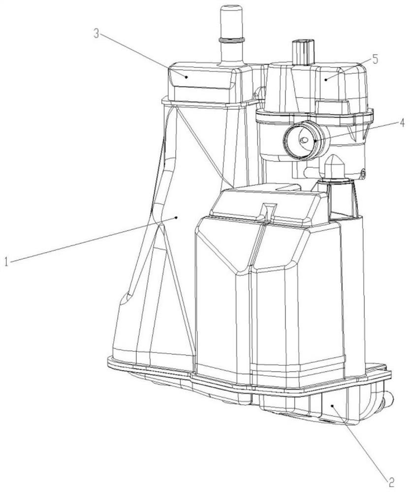
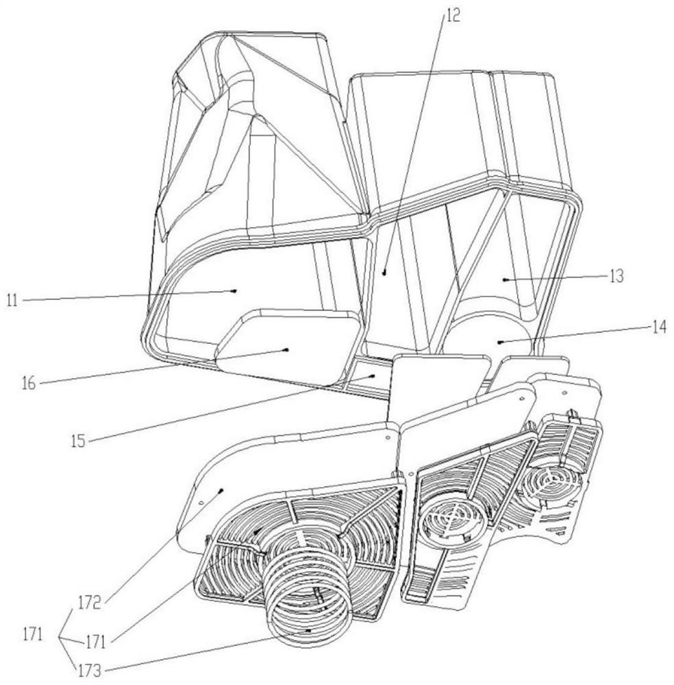
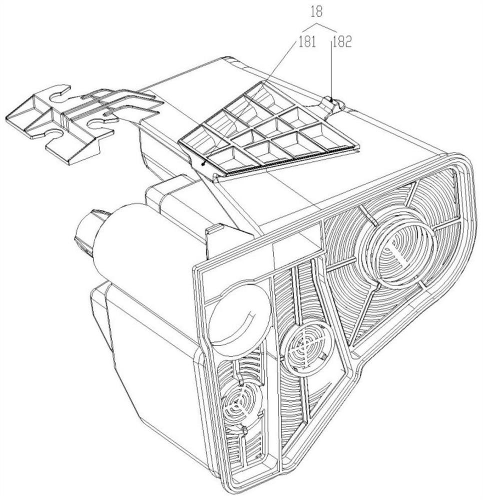
[0025] like figure 1Shown is a perspective view of the present invention, including a casing 1, a bottom cover 2, an adsorption port structure 3, an air outlet structure 4, and a leakage diagnosis module 5. The bottom cover 2 is arranged below the casing 1, and the adsorption port structure 3 Disposed above the casing 1, the air outlet structure 4 is disposed on the casing 1 at the side of the adsorption port structure 3, and the leakage diagnosis module 5 is disposed above the air outlet structure 4; figure 2 and as image 3 Shown are an exploded perspective view of the housing 1 and perspective views from different perspectives, in which a first cavity 11, a second cavity 12, a third cavity 13, a fourth cavity 14, and a flow channel 15 are arranged side by side. The upper positions of the second cavity 12 and the third cavity 13 communicate with each other.

[0026] The type of toner in the first cavity 11 and the second cavity 12 is Bax1500; the type of toner in the thir...


PUM


Abstract

A novel carbon tank structure meeting a complex vehicle body comprises a shell, a bottom cover, an adsorption opening structure, an atmosphere outlet structure and a leakage diagnosis module. A first cavity, a second cavity, a third cavity, a fourth cavity and a flow channel are arranged in the shell side by side. In the using process of an automobile, oil steam in the fuel tank is discharged through the air outlet of the fuel tank, enters the shell along the adsorption opening structure to be subjected to hydrocarbon adsorption treatment and then is discharged from the atmosphere outlet structure, and the leakage diagnosis module monitors the pressure of the shell in real time, so that the situations of leakage and the like are found in time. The first cavity, the second cavity, the third cavity and the fourth cavity are formed in the shell, the first cavity, the second cavity and the third cavity are filled with the carbon powder, compared with a traditional automobile carbon tank with two cavities, oil vapor flows through the carbon powder in the first cavity, the second cavity and the third cavity, the path length of the carbon powder is lengthened, and therefore the carbon powder in the first cavity, the second cavity and the third cavity is more uniform. And the oil steam can be fully adsorbed by the carbon powder.

Description

technical field [0001] The invention relates to the field of automobiles, in particular to a novel carbon canister structure that satisfies complex vehicle bodies. Background technique [0002] The vehicle carbon canister structure is used as the exhaust passage of the fuel system, and its main function is to absorb the fuel vapor generated by volatilization in the fuel system, so as to prevent the vehicle's hydrocarbon emissions from exceeding the standard. [0003] Moreover, after the carbon canister absorbs oil vapor, the engine will perform negative pressure extraction on the carbon canister during operation, so that the adsorbed hydrocarbons are reused by the engine again, and the carbon powder in the carbon canister can be continuously used. [0004] At present, the carbon canister structure used in the market has the following shortcomings: 1) The traditional automobile carbon canister structure is generally a two-chamber carbon powder cavity, and the oil vapor flows ...

Claims


Application Information

Patent Timeline
Patent Type & Authority Applications(China)
IPC IPC(8): F02M25/08
CPCF02M25/0854Y02T10/40
Inventor 张生周彪胡安东谭亚
Owner STANT AUTOMOTIVE SYST SUZHOU
Why Eureka
Try Eureka