End shaft sealing structure of compressor

A sealing structure and compressor technology, applied in the field of compressors, can solve the problems of inability to completely block water from entering outwards, bearing corrosion and damage, etc., and achieve the effects of good sealing, low friction and long service life.

Pending Publication Date: 2022-07-12
无锡索贝克精密机械有限公司
View PDF0 Cites 0 Cited by
  • Summary
  • Abstract
  • Description
  • Claims
  • Application Information

AI Technical Summary

Problems solved by technology

[0002] When the oil-free screw compressor is running, there is a negative pressure at both ends of the rotating shaft. When it stops, the two ends of the rotating shaft will generate a high pressure of several atmospheres for a few seconds. The rotors are sealed and cooled, which causes the high-pressure gas to press the water in the compressor into the bearing at the shaft end when the machine is shut down, causing the bearing to be corroded and damaged
The existing shaft end seal structure generally adopts a labyrinth seal, which cannot completely prevent water from entering the bearing at the moment of normal operation and shutdown.

Method used


Image

  • End shaft sealing structure of compressor
  • End shaft sealing structure of compressor
  • End shaft sealing structure of compressor

Examples


Embodiment 1

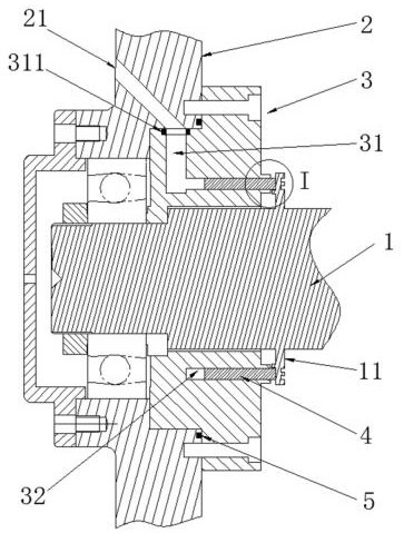
[0020] combine Figure 1-2 As shown, a compressor end shaft sealing structure includes a rotating shaft 1 and an end cover 2, and a bearing is arranged between the two, so that the rotating shaft 1 can rotate. The inner side of the end cover 2 is sealed with a sealing member 3, and a plurality of through holes can be provided on the sealing member 3, and a plurality of threaded holes are arranged on the inner side of the end cover 2, and the two are fixed together by bolts, and the end cover 2 is in the A second sealing ring 5 is provided on the inner side of the threaded hole, so that the two are connected in a sealed manner. The end cover 2 is provided with a first ventilation hole 21 for connecting the compressed gas source, the sealing member 3 is provided with a second ventilation hole 31 which communicates with the first ventilation hole 21, and the sealing member 3 is provided with a second ventilation hole 31 communicating with the first ventilation hole 21. A sliding...

Embodiment 2

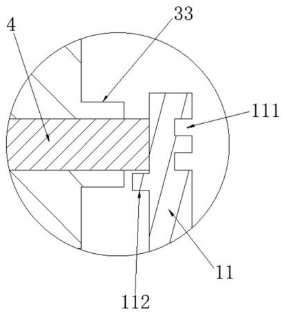
[0026] combine figure 2 As shown, this embodiment is basically the same as Embodiment 1, the difference is that the sealing member 3 is provided with a support portion 33 at the outer end of the sliding cavity 32, and the supporting portion 33 is distributed on both sides of the sliding cavity 32. Cylindrical boss. On the one hand, the support part 33 can support the outer end of the cylindrical sealing ring 4 to reduce its deformation under pressure; figure 2 It can be seen that the wall thickness of the support portion 33 is relatively small, which can improve the heat dissipation efficiency when it is in contact with water.

Embodiment 3

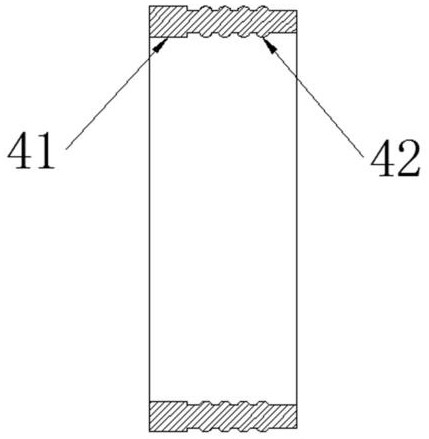
[0028] combine Figure 3-4 As shown, this embodiment is basically the same as Embodiment 1, the difference is that the end of the cylindrical sealing ring 4 close to the second ventilation hole 31 is provided with a pushing portion 41, and the inner and outer surfaces of the pushing portion 41 are respectively convex. For the inner and outer surfaces of the cylindrical sealing ring 4 , a plurality of convex rings 42 are also provided on the inner and outer sides of the cylindrical sealing ring 4 . Under this structure, the pushing portion 41 and the convex ring 42 and the two sides of the sliding cavity 32 can form a larger pressure, the deformation is larger, and the sealing effect is better, and the main body of the cylindrical sealing ring 4 may not be in contact with the sliding cavity 32. Pressure or a certain gap is formed on both sides of the seal, so that the contact area between the two is smaller and the frictional force is smaller, so that the cylindrical sealing ri...


PUM


Abstract

The invention relates to the technical field of compressors, in particular to a compressor end shaft sealing structure. Comprising a rotating shaft and an end cover which are rotationally connected, the inner side of the end cover is connected with a sealing piece in a sealed mode, the end cover is provided with a first vent hole used for being connected with a compressed gas source, the sealing piece is provided with a second vent hole communicated with the first vent hole, and the sealing piece is provided with a sliding cavity coaxial with the rotating shaft. The cross section of the sliding cavity is in a circular ring shape, the second vent hole is communicated with the end, close to the end cover, of the sliding cavity, a cylindrical sealing ring is connected into the sliding cavity in a sliding and sealing mode, a circular ring-shaped sealing piece is arranged on the rotating shaft, and one end of the cylindrical sealing ring makes contact with one side of the sealing piece. The sealing structure has good sealing performance, and water can be prevented from entering the bearing outwards.

Description

technical field [0001] The invention relates to the technical field of compressors, in particular to a compressor end shaft sealing structure. Background technique [0002] When the oil-free screw compressor is running, there is negative pressure at both ends of its rotating shaft. When it stops, both ends of the rotating shaft will generate a high pressure of several atmospheres for several seconds. The rotors play a role in sealing and cooling, which leads to the high-pressure gas pressing the water in the compressor into the bearing at the shaft end during shutdown, causing the bearing to rust and damage. The existing shaft end sealing structure generally adopts a labyrinth seal, which cannot completely prevent water from entering the bearing from the outside during normal operation and at the moment of shutdown. SUMMARY OF THE INVENTION [0003] The technical problem to be solved by the present invention is aimed at the above-mentioned technical deficiencies, and prov...

Claims


Application Information

Patent Timeline
Patent Type & Authority Applications(China)
IPC IPC(8): F16J15/16
CPCF16J15/164
Inventor 刘秀明
Owner 无锡索贝克精密机械有限公司
Why Eureka
Try Eureka