MOS tube assembly and assembling device thereof

A technology of MOS tubes and components, applied in the field of MOS tube components and their assembly devices, can solve the problems of low assembly efficiency, affecting heat dissipation effect, cumbersome screw installation process, etc., and achieve the effect of improving assembly efficiency

Active Publication Date: 2022-07-12
上海晶岳电子有限公司
View PDF6 Cites 0 Cited by
  • Summary
  • Abstract
  • Description
  • Claims
  • Application Information

AI Technical Summary

Problems solved by technology

[0002] In the prior art, MOS tubes are generally fixed on the radiator by screws. The disadvantage of this assembly structure is that the installation process of the screws is relatively cumbersome, and it needs to be operated with the help of an electric screwdriver. The single operation cycle is long and the assembly efficiency is low; In addition, the screw is generally only installed at one end of the MOS tube. The temperature of the MOS tube changes repeatedly during the working process, which may cause slight deformation of the radiator, resulting in an empty drum between the MOS tube and the radiator, which affects the heat dissipation effect.

Method used


Image

  • MOS tube assembly and assembling device thereof
  • MOS tube assembly and assembling device thereof
  • MOS tube assembly and assembling device thereof

Examples


Embodiment Construction

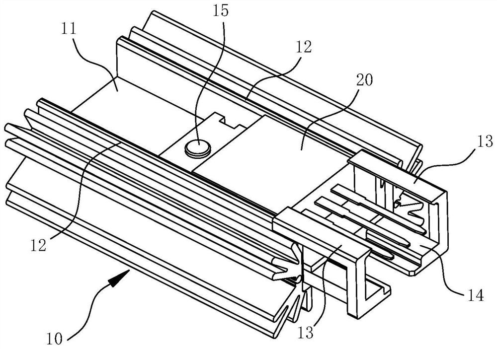
[0035] The embodiments of the present invention are described below through specific specific examples, and those skilled in the art can easily understand other advantages and effects of the present invention from the contents disclosed in this specification. The present invention can also be implemented or applied through other different specific embodiments, and various details in this specification can also be modified or changed based on different viewpoints and applications without departing from the spirit of the present invention. It should be noted that the following embodiments and features in the embodiments may be combined with each other under the condition of no conflict.

[0036] It should be noted that the diagrams provided in the following embodiments are only used to illustrate the basic concept of the present invention in a schematic way, so the diagrams only show the components related to the present invention rather than the number, shape and For dimension ...


PUM


Abstract

The invention belongs to the technical field of semiconductor processing, and particularly relates to an MOS tube assembly and an assembling device thereof.The MOS tube assembly comprises an MOS tube and a heat dissipation block, the heat dissipation block comprises a mounting plate, heat dissipation fins arranged in a radial shape are arranged on the two sides of the mounting plate, positioning columns protruding out of the plate face of the mounting plate are arranged on the mounting plate, and the positioning columns are arranged on the mounting plate. The MOS tube is provided with a positioning hole matched with the positioning column; and a clamping mechanism is arranged on the heat dissipation block. According to the invention, the positioning column is used for preliminarily positioning the MOS tube, then the clamping mechanism is used for integrally pressing the MOS tube on the heat dissipation block, the MOS tube is integrally restrained, and hollowing does not easily occur between the MOS tube and the heat dissipation block; in addition, linkage between the downward pressing action of the MOS tube and the clamping action of the clamping mechanism is achieved through the linkage mechanism, the clamping mechanism can be automatically triggered to act while the MOS tube is pressed on the heat dissipation block, no extra assembling tool needs to be used, and the assembling efficiency between the MOS tube and the heat dissipation block is improved.

Description

technical field [0001] The invention belongs to the technical field of semiconductor processing, and in particular relates to a MOS tube assembly and an assembling device thereof. Background technique [0002] In the prior art, the MOS tube is generally fixed on the radiator by screws. The defect of this assembly structure is that the installation process of the screws is cumbersome and requires the help of an electric batch rod to operate, the single operation cycle is long, and the assembly efficiency is low; In addition, the screw is generally only installed at one end of the MOS tube. The temperature of the MOS tube changes repeatedly during the working process, which may cause the radiator to deform slightly, resulting in a hollow between the MOS tube and the radiator, which affects the heat dissipation effect. SUMMARY OF THE INVENTION [0003] In view of the above-mentioned shortcomings of the prior art, an object of the present invention is to provide a MOS tube ass...

Claims


Application Information

Patent Timeline
Patent Type & Authority Applications(China)
IPC IPC(8): H01L23/367H01L23/40H01L29/78H01L21/67
CPCH01L23/367H01L23/40H01L29/78H01L21/67121Y02E60/10
Inventor 朱金伟
Owner 上海晶岳电子有限公司
Why Eureka
Try Eureka