Movable distribution box with good heat dissipation effect

A heat-dissipating, mobile technology, applied in substation/distribution device housing, electrical components, substation/switch layout details, etc. problems such as movement, to reduce limitations, save power, and improve the comprehensiveness and uniformity of cooling

Pending Publication Date: 2022-07-12
徐博
View PDF1 Cites 1 Cited by
  • Summary
  • Abstract
  • Description
  • Claims
  • Application Information

AI Technical Summary

Problems solved by technology

[0003] The existing distribution box is not easy to move. When changing the work site, it is necessary to manually lift or use lifting tools to move the distribution box. During the transportation process, collisions are likely to occur and the internal equipment will be damaged. The internal equipment emits a large amount of heat, which causes the temperature in the distribution box to rise, and the internal equipment works in a high-temperature environment for a long time, which is prone to aging or damage to the circuit, which shortens the service life of the distribution box;
[0004] For example, CN107181184A discloses a power distribution cabinet for improving heat dissipation effect in the existing distribution box refrigeration equipment, which includes left electrical parts installed on the left mounting board and right electrical parts installed on the right mounting board. There are several heat dissipation fins on the board and the right mounting plate. The ends of the heat dissipation fins are provided with a heat dissipation plane. The width of the heat dissipation fins towards the direction of the heat dissipation plane gradually increases. The structure of the cabinet is simple, and the heat dissipation effect of the cabinet is improved by optimizing the structure of the heat dissipation fins. The heat dissipation is only a simple purge at the bottom, so it cannot effectively improve the heat dissipation effect

Method used


Image

  • Movable distribution box with good heat dissipation effect
  • Movable distribution box with good heat dissipation effect
  • Movable distribution box with good heat dissipation effect

Examples


Embodiment Construction

[0025] The technical solutions in the embodiments of the present invention will be clearly and completely described below with reference to the accompanying drawings in the embodiments of the present invention. Obviously, the described embodiments are only a part of the embodiments of the present invention, but not all of the embodiments.

[0026] In the description of this patent, it should be noted that, unless otherwise expressly specified and limited, the terms "installed", "connected", "connected" and "arranged" should be understood in a broad sense. , it can also be detachably connected and set, or integrally connected and set. For those of ordinary skill in the art, the specific meanings of the above terms in this patent can be understood according to specific situations.

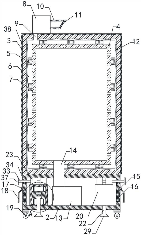
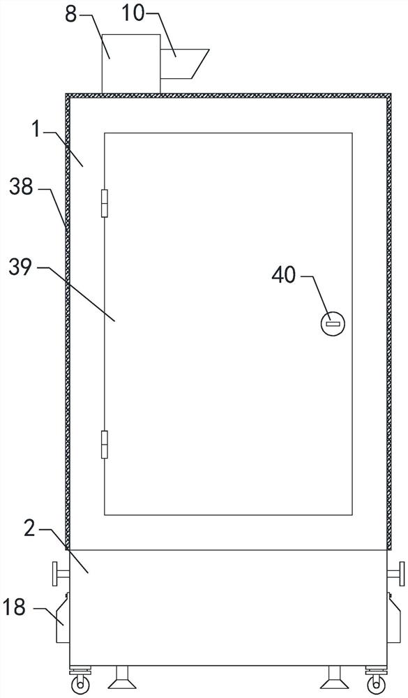
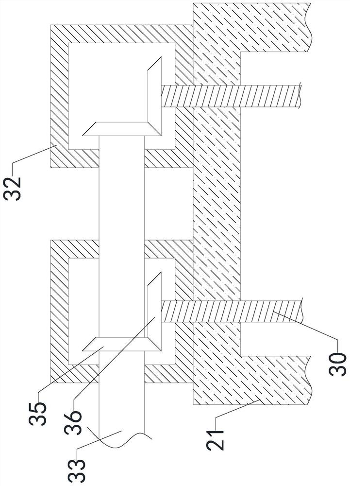
[0027] refer to Figure 1-4 , a movable distribution box with good heat dissipation effect, including a first box 1 and a second box 2, the first box 1 includes an outer shell 3 and an inner shell 4...


PUM


Abstract

A movable distribution box with a good heat dissipation effect disclosed by the present invention comprises a first box body and a second box body, the first box body comprises an outer shell and an inner shell, the inner shell is arranged in the outer shell, the outer shell is fixedly connected with the inner shell through a connection block, a cavity is formed between the outer shell and the inner shell, and the inner shell is arranged in the cavity. A plurality of through holes are evenly formed in the left end, the right end and the rear end of the inner shell, the top end of the outer shell is fixedly connected with an air cooler, the output end of the air cooler is communicated with the cavity through an air outlet pipe, and the input end of the air cooler is connected with an air inlet pipe; the power distribution box can keep the temperature suitable for working of internal equipment in the power distribution box, prolongs the service life of the power distribution box, facilitates the movement of the power distribution box, facilitates the stable supporting of the power distribution box in a working area with a complex terrain, improves the working stability of the power distribution box, improves the use adaptability of the power distribution box, and improves the working efficiency. And the use limitation is reduced.

Description

technical field [0001] The invention specifically relates to the technical field of distribution boxes, in particular to a movable distribution box with good heat dissipation effect. Background technique [0002] The distribution box is a low-voltage power distribution device that assembles switchgear, measuring instruments, protective appliances and auxiliary equipment in a closed or semi-closed metal cabinet or on the screen according to the electrical wiring requirements. [0003] The existing distribution box is not easy to move. When changing the workplace, it needs to be manually lifted or moved with a lifting tool. During the transportation process, it is very easy to collide and cause damage to the internal equipment. The internal equipment dissipates a lot of heat, which leads to an increase in the temperature in the distribution box, and the internal equipment works in a high temperature environment for a long time, which is prone to line aging or damage, which sho...

Claims


Application Information

Patent Timeline
Patent Type & Authority Applications(China)
IPC IPC(8): H02B1/46H02B1/56H02B1/52H02B1/28H02B1/50H02B1/54
CPCH02B1/46H02B1/565H02B1/52H02B1/28H02B1/50H02B1/54Y02A30/14
Inventor 徐博
Owner 徐博
Why Eureka
Try Eureka