
Sounding device and sounding component

A sound-emitting device and sound-emitting element technology, applied in electrical components, sensor parts, sensors, etc., can solve problems such as carbon nanotubes that have not yet been discovered, and achieve the effects of cost reduction, rapid temperature rise, and small thermal hysteresis.

Active Publication Date: 2009-12-16
TSINGHUA UNIV +1
View PDF1 Cites 12 Cited by
  • Summary
  • Abstract
  • Description
  • Claims
  • Application Information

AI Technical Summary

Problems solved by technology

However, carbon nanotubes have not been found in the prior art to be used in the acoustic field as sound-generating components

Method used


Image

  • Sounding device and sounding component
  • Sounding device and sounding component
  • Sounding device and sounding component

Examples


preparation example Construction

[0039] The preparation method of the carbon nanotube film in the first embodiment of the present invention mainly includes the following steps:

[0040] Step 1: providing a carbon nanotube array, preferably, the array is a super-aligned carbon nanotube array.

[0041] The carbon nanotube array provided in the embodiment of the present invention is one or more of a single-wall carbon nanotube array, a double-wall carbon nanotube array, and a multi-wall carbon nanotube array. In this embodiment, the preparation method of the super-parallel carbon nanotube array adopts the chemical vapor deposition method, and its specific steps include: (a) providing a flat substrate, which can be a P-type or N-type silicon substrate, or can be formed There is the silicon substrate of oxide layer, and the present embodiment preferably adopts the silicon substrate of 4 inches; (b) uniformly forms a catalyst layer on the substrate surface, and this catalyst layer material can be selected iron (Fe)...


PUM


Abstract

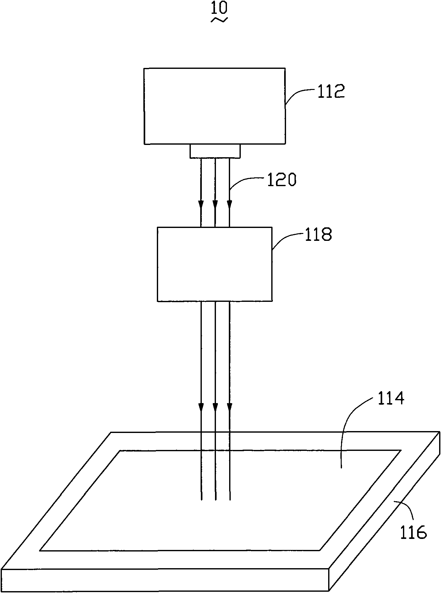
The invention relates to a sounding device, which comprises an electromagnetic signal input device and a sounding component, wherein the sounding component comprises at least a carbon nanotube membrane including a plurality of preferred orientation arranged carbon nanotube and contacting with a medium; the electromagnetic signal input device transmits electromagnetic signal to the carbon nanotubemembrane which heats through adsorbing the electromagnetic signal, so as to heat the medium to send out sound wave. The invention also relates to a sounding component.

Description

technical field [0001] The invention relates to a sounding device and a sounding element, in particular to a sounding device and a sounding element based on carbon nanotubes. Background technique [0002] The sounding device generally consists of a signal input device and a sounding element. The electrical signal is input to the sound generating element through the signal input device, and then the sound is emitted. The sound emitting element in the prior art is generally a loudspeaker. The loudspeaker is an electro-acoustic device that converts electrical signals into sound signals. Specifically, the speaker can convert audio electric power signals within a certain range into audible sounds with less distortion and sufficient sound pressure level. There are many types of speakers. Although they work in different ways, they generally push the surrounding air by generating mechanical vibrations, causing the air medium to fluctuate so as to realize the conversion of "electr...

Claims


Application Information

Patent Timeline
Patent Type & Authority Applications(China)
IPC IPC(8): H04R23/00
Inventor 姜开利肖林陈卓范守善
Owner TSINGHUA UNIV
Learn More